Analog-to-digital converter (ADC) RM0390
390/1328 RM0390 Rev 4
Note: The software can write to these registers when an ADC conversion is ongoing. The
programmed value will be effective when the next conversion is complete. Writing to this
register is performed with a write delay that can create uncertainty on the effective time at
which the new value is programmed.
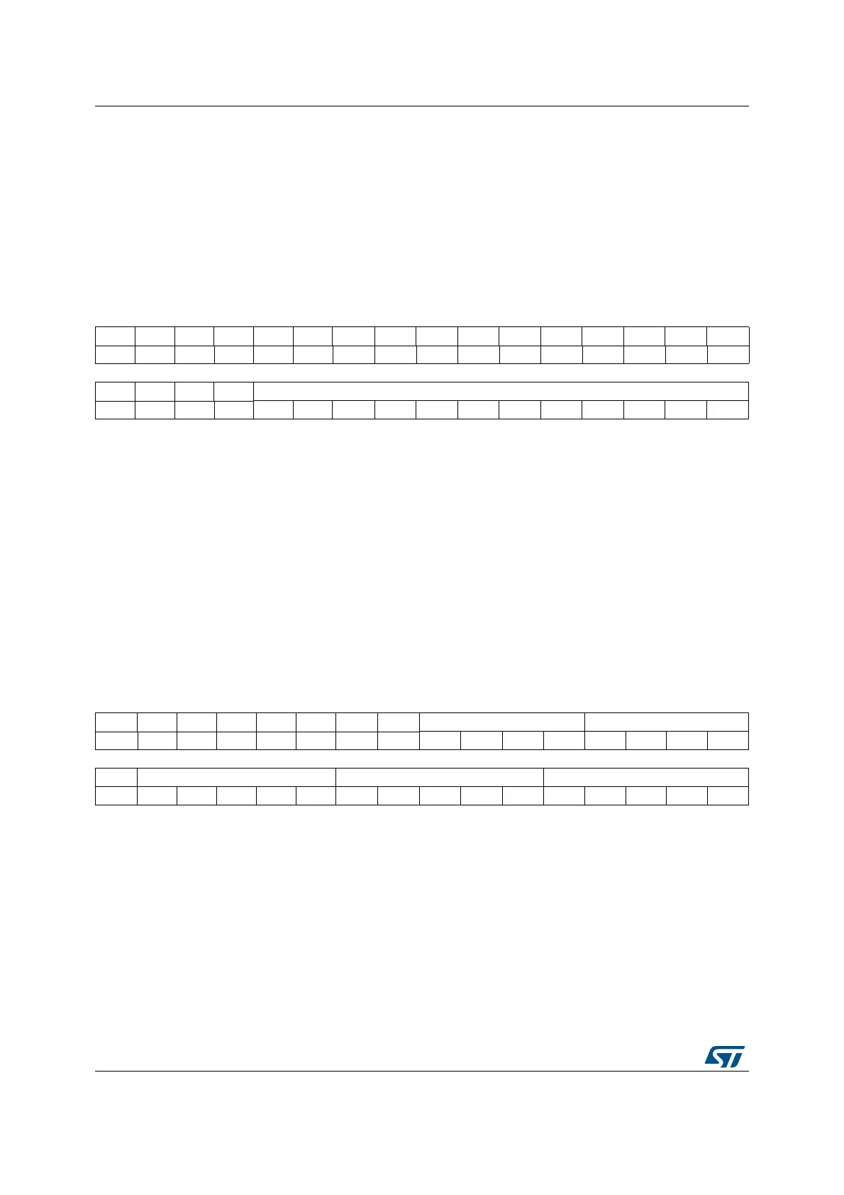
13.13.8 ADC watchdog lower threshold register (ADC_LTR)
Address offset: 0x28
Reset value: 0x0000 0000
Note: The software can write to these registers when an ADC conversion is ongoing. The
programmed value will be effective when the next conversion is complete. Writing to this
register is performed with a write delay that can create uncertainty on the effective time at
which the new value is programmed.
13.13.9 ADC regular sequence register 1 (ADC_SQR1)
Address offset: 0x2C
Reset value: 0x0000 0000
31 30 29 28 27 26 25 24 23 22 21 20 19 18 17 16
Res. Res. Res. Res. Res. Res. Res. Res. Res. Res. Res. Res. Res. Res. Res. Res.
15 14 13 12 11 10 9 8 7 6 5 4 3 2 1 0
Res. Res. Res. Res. LT[11:0]
rw rw rw rw rw rw rw rw rw rw rw rw
Bits 31:12 Reserved, must be kept at reset value.
Bits 11:0 LT[11:0]: Analog watchdog lower threshold
These bits are written by software to define the lower threshold for the analog watchdog.
31 30 29 28 27 26 25 24 23 22 21 20 19 18 17 16
Res. Res. Res. Res. Res. Res. Res. Res. L[3:0] SQ16[4:1]
rw rw rw rw rw rw rw rw
15 14 13 12 11 10 9 8 7 6 5 4 3 2 1 0
SQ16_0 SQ15[4:0] SQ14[4:0] SQ13[4:0]
rw rw rw rw rw rw rw rw rw rw rw rw rw rw rw rw
 Loading...


