Universal synchronous asynchronous receiver transmitter (USART) RM0390
796/1328 RM0390 Rev 4
– Receive data register full
– Idle line received
– Overrun error
– Framing error
– Noise error
– Parity error
• Multiprocessor communication - enter into mute mode if address match does not occur
• Wake up from mute mode (by idle line detection or address mark detection)
• Two receiver wakeup modes: Address bit (MSB, 9
th
bit), Idle line
25.3 USART implementation
This section describes the full set of features implemented in USART1. Refer to Table 145:
USART features for the differences between USART instances.
25.4 USART functional description
The interface is externally connected to another device by three pins (see Figure 279). Any
USART bidirectional communication requires a minimum of two pins: Receive Data In (RX)
and Transmit Data Out (TX):
RX: Receive Data Input is the serial data input. Oversampling techniques are used for data
recovery by discriminating between valid incoming data and noise.
TX: Transmit Data Output. When the transmitter is disabled, the output pin returns to its I/O
port configuration. When the transmitter is enabled and nothing is to be transmitted, the TX
pin is at high level. In single-wire and smartcard modes, this I/O is used to transmit and
receive the data (at USART level, data are then received on SW_RX).
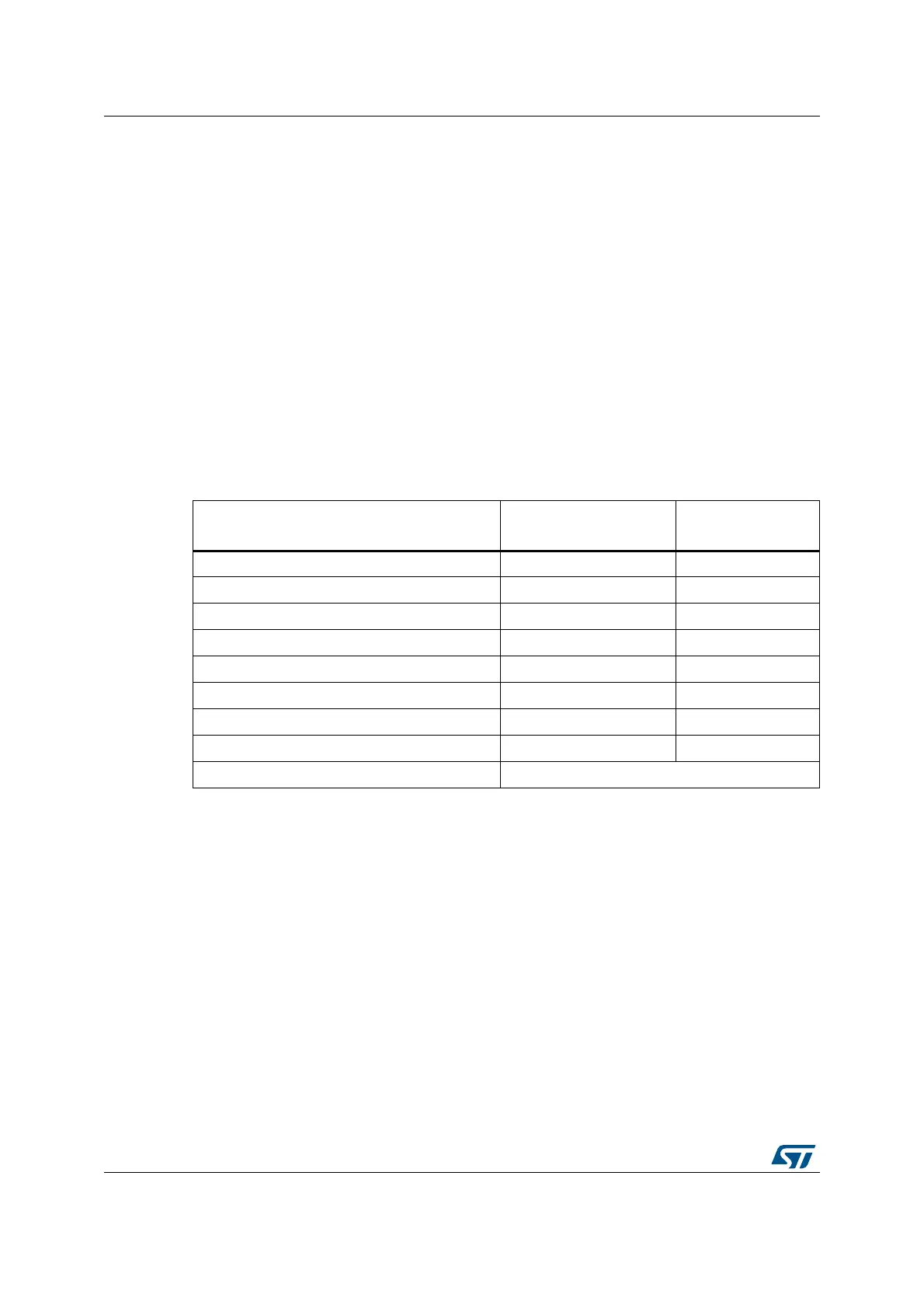
Table 145. USART features
USART modes/features
(1)
1. X = supported.
USART1, USART2,
USART3, USART6
UART4, UART5
Hardware flow control for modem X X
Continuous communication using DMA X X
Multiprocessor communication X X
Synchronous mode X -
Smartcard mode X -
Single-wire half-duplex communication X X
IrDA SIR ENDEC block X X
LIN mode X X
USART data length 8 or 9 bits