Digital camera interface (DCMI) RM0390
432/1328 RM0390 Rev 4
If the DCMI_VSYNC signal goes active before the number of lines is specified in the
DCMI_CWSIZE register, then the capture stops and an IT_FRAME interrupt is generated
when enabled.
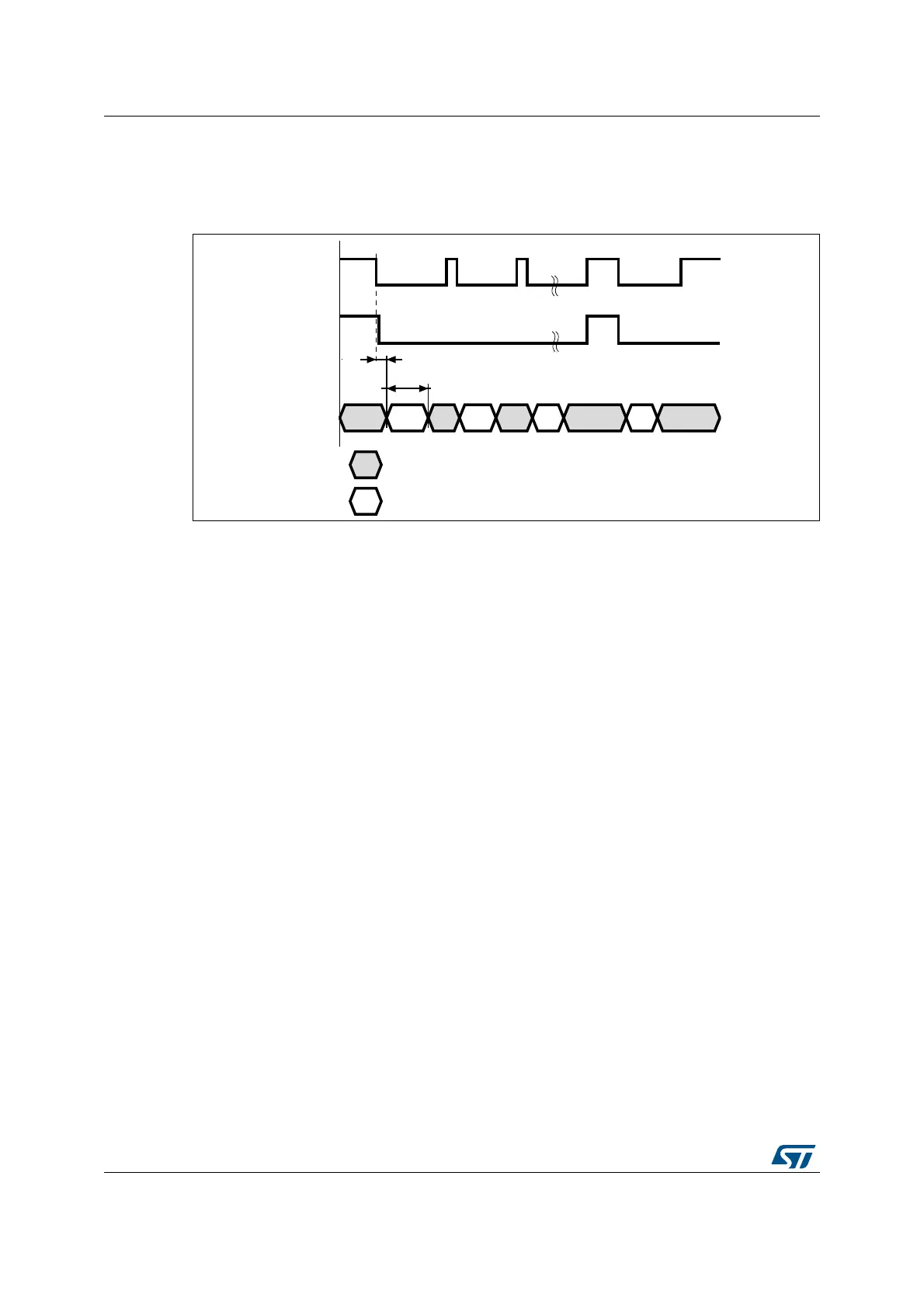
Figure 108. Data capture waveforms
1. Here, the active state of DCMI_HSYNC and DCMI_VSYNC is 1.
2. DCMI_HSYNC and DCMI_VSYNC can change states at the same time.
15.4.7 JPEG format
To allow JPEG image reception, it is necessary to set the JPEG bit in the DCMI_CR register.
JPEG images are not stored as lines and frames, so the DCMI_VSYNC signal is used to
start the capture while DCMI_HSYNC serves as a data enable signal. The number of bytes
in a line may not be a multiple of 4, you should therefore be careful when handling this case
since a DMA request is generated each time a complete 32-bit word has been constructed
from the captured data. When an end of frame is detected and the 32-bit word to be
transferred has not been completely received, the remaining data are padded with ‘0s’ and a
DMA request is generated.
The crop feature and embedded synchronization codes cannot be used in the JPEG format.
15.4.8 FIFO
Input mode
A four-word FIFO is implemented to manage data rate transfers on the AHB. The DCMI
features a simple FIFO controller with a read pointer incremented each time the camera
interface reads from the AHB, and a write pointer incremented each time the camera
interface writes to the FIFO. There is no overrun protection to prevent the data from being
overwritten if the AHB interface does not sustain the data transfer rate.
In case of overrun or errors in the synchronization signals, the FIFO is reset and the DCMI
interface waits for a new start of frame.
'&0,B+6<1&
'&0,B96<1&
069
&$3&17
+2))&17
'DWDQRWFDSWXUHGLQWKLVSKDVH
'DWDFDSWXUHGLQWKLVSKDVH
 Loading...


