RM0390 Rev 4 453/1328
RM0390 Advanced-control timers (TIM1&TIM8)
520
16.3.2 Counter modes
Upcounting mode
In upcounting mode, the counter counts from 0 to the auto-reload value (content of the
TIMx_ARR register), then restarts from 0 and generates a counter overflow event.
If the repetition counter is used, the update event (UEV) is generated after upcounting is
repeated for the number of times programmed in the repetition counter register plus one
(TIMx_RCR+1). Else the update event is generated at each counter overflow.
Setting the UG bit in the TIMx_EGR register (by software or by using the slave mode
controller) also generates an update event.
The UEV event can be disabled by software by setting the UDIS bit in the TIMx_CR1
register. This is to avoid updating the shadow registers while writing new values in the
preload registers. Then no update event occurs until the UDIS bit has been written to 0.
However, the counter restarts from 0, as well as the counter of the prescaler (but the
prescale rate does not change). In addition, if the URS bit (update request selection) in
TIMx_CR1 register is set, setting the UG bit generates an update event UEV but without
setting the UIF flag (thus no interrupt or DMA request is sent). This is to avoid generating
both update and capture interrupts when clearing the counter on the capture event.
When an update event occurs, all the registers are updated and the update flag (UIF bit in
TIMx_SR register) is set (depending on the URS bit):
• The repetition counter is reloaded with the content of TIMx_RCR register,
• The auto-reload shadow register is updated with the preload value (TIMx_ARR),
• The buffer of the prescaler is reloaded with the preload value (content of the TIMx_PSC
register).
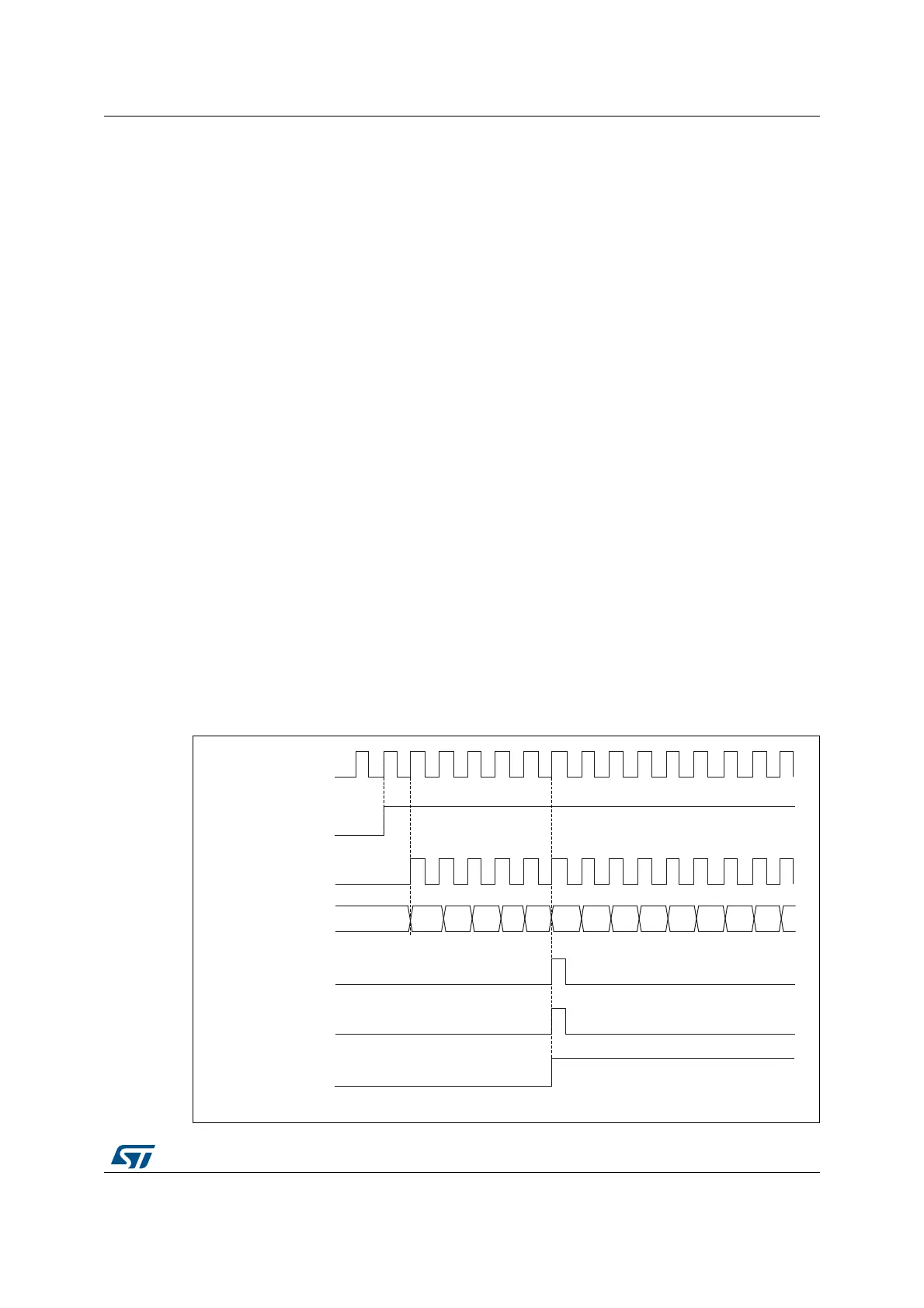
The following figures show some examples of the counter behavior for different clock
frequencies when TIMx_ARR=0x36.
Figure 113. Counter timing diagram, internal clock divided by 1
ϬϬ ϬϮ Ϭϯ Ϭϰ Ϭϱ Ϭϲ Ϭϳϯϯ ϯϰ ϯϱ ϯϲϯϭ
069
<ͺW^
EdͺE
dŝŵĞƌĐůŽĐŬс<ͺEd
ŽƵŶƚĞƌƌĞŐŝƐƚĞƌ
hƉĚĂƚĞĞǀĞŶƚ;hsͿ
ŽƵŶƚĞƌŽǀĞƌĨůŽǁ
hƉĚĂƚĞŝŶƚĞƌƌƵƉƚĨůĂŐ;h/&Ϳ
ϬϭϯϮ