RM0390 Rev 4 901/1328
RM0390 SPDIF receiver interface (SPDIFRX)
929
Figure 343 gives a detailed view of the SPDIFRX decoder.
Figure 343. SPDIFRX decoder
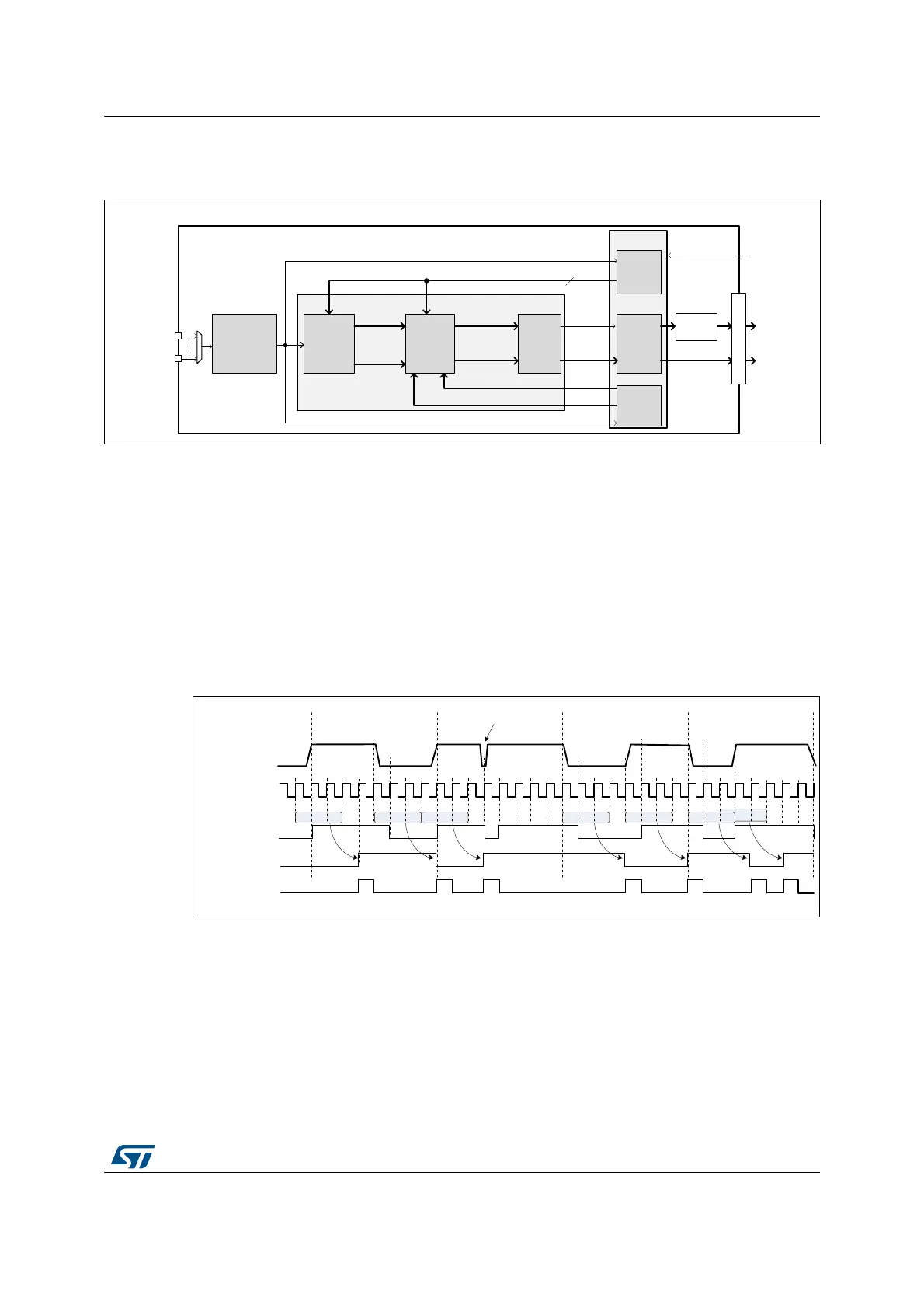
Noise filtering & rising/falling edge detection
The S/PDIF signal received on the selected SPDIFRX_IN is re-sampled using the
SPDIFRX_CLK clock (acquisition clock). A simple filtering is applied in order cancel spurs.
This is performed by the stage detecting the edge transitions. The edge transitions are
detected as follow:
• A rising edge is detected when the sequence 0 followed by two 1 is sampled.
• A falling edge is detected when the sequence 1 followed by two 0 is sampled.
• After a rising edge, a falling edge sequence is expected.
• After a falling edge, a rising edge sequence is expected.
Figure 344. Noise filtering and edge detection
Longest and shortest transition detector
The longest and shortest transition detector block detects the maximum (MAX_CNT)
and minimum (MIN_CNT) duration between two transitions. The TRCNT counter is used to
measure the time interval duration. It is clocked by the SPDIFRX_CLK signal. On every
transition pulse, the counter value is stored and the counter is reset to start counting again.
The maximum duration is normally found during the preamble period. This maximum
duration is sent out as MAX_CNT. The minimum duration is sent out as MIN_CNT.
63',)5;B)(
1RLVHILOWHULQJ
(GJHGHWHFWLRQ
/RQJHVW
VKRUWHVW
WUDQVLWLRQ
GHWHFWRU
75&17
ELWV
7UDQVLWLRQ
FRGHU
3UHDPEOH
GHWHFWRU
'DWD
3DFNLQJ
63',)5;B'(&
63',)5;B6(4
0$;B&17
WUDQVLWLRQBSXOVH
WUDQVLWLRQBZLGWKBFRXQW
SUHDPEOHBLQIR
WUDQVBLQIR
%LSKDVH
GHFRGHU
GDWD
GDWDBYDOLG
6<1&
5;B%8)
63',)5;B,1>@
63',)5;B'&
63',)5;B&/.
0,1B&17
FWUOBFK
63',)5;B,1>Q@
GDWD
),1(
6<1&
:,'7+
:,'7+
WUDQVLWLRQBSXOVH
06Y9
63',)5;B,1>Q@
63',)5;B&/.
*OLWFK
6 6 6 6
UHVDPSOHGLQSXW
ILOWHUHGLQSXW
WUDQVLWLRQBSXOVH
06Y9
 Loading...


