RM0390 Rev 4 555/1328
RM0390 General-purpose timers (TIM2 to TIM5)
581
you want in the timer counters. The timers can easily be reset by software using the UG bit
in the TIMx_EGR registers.
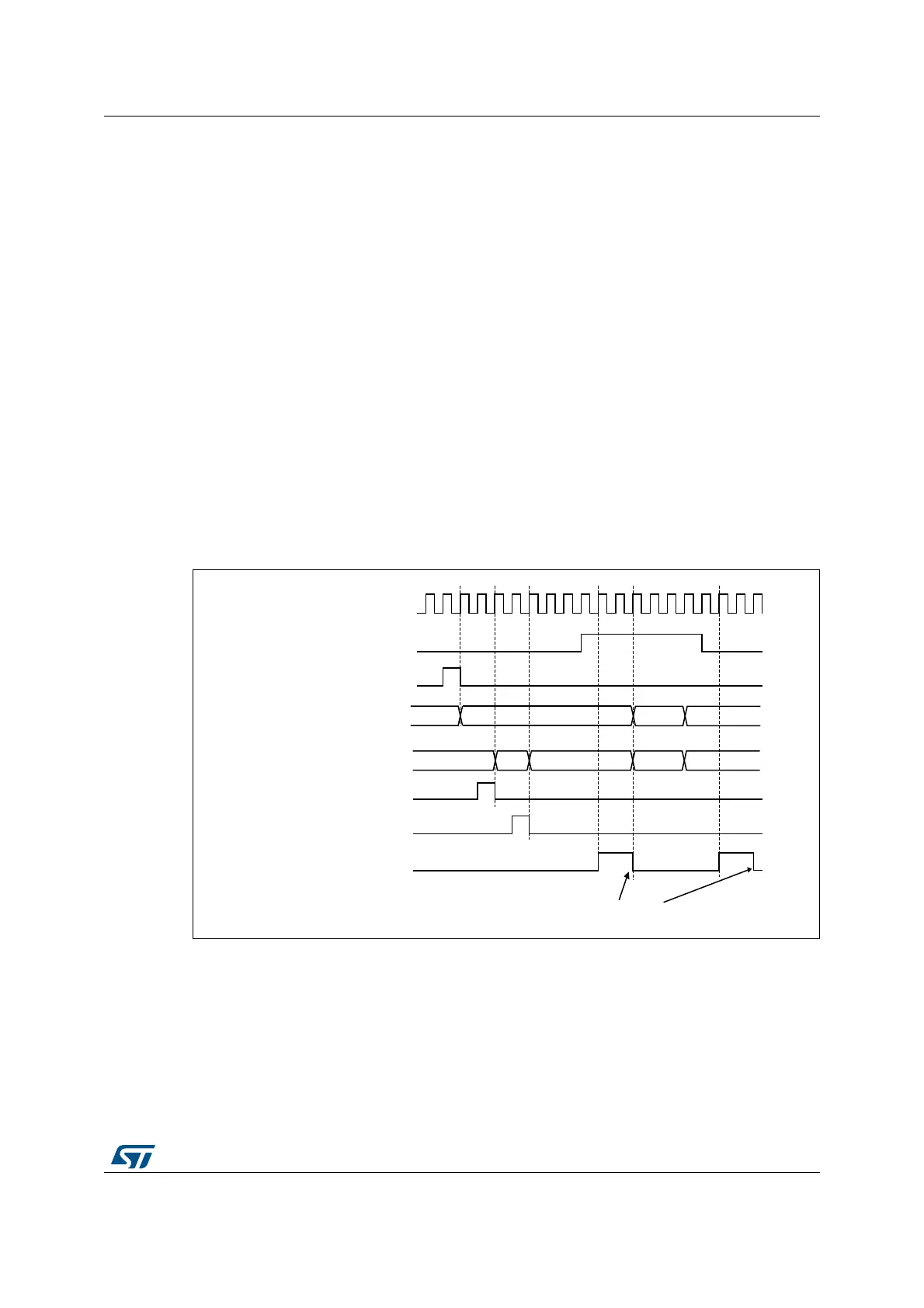
In the next example, we synchronize Timer 1 and Timer 2. Timer 1 is the master and starts
from 0. Timer 2 is the slave and starts from 0xE7. The prescaler ratio is the same for both
timers. Timer 2 stops when Timer 1 is disabled by writing ‘0 to the CEN bit in the TIM1_CR1
register:
• Configure Timer 1 master mode to send its Output Compare 1 Reference (OC1REF)
signal as trigger output (MMS=100 in the TIM1_CR2 register).
• Configure the Timer 1 OC1REF waveform (TIM1_CCMR1 register).
• Configure Timer 2 to get the input trigger from Timer 1 (TS=000 in the TIM2_SMCR
register).
• Configure Timer 2 in gated mode (SMS=101 in TIM2_SMCR register).
• Reset Timer 1 by writing ‘1 in UG bit (TIM1_EGR register).
• Reset Timer 2 by writing ‘1 in UG bit (TIM2_EGR register).
• Initialize Timer 2 to 0xE7 by writing ‘0xE7’ in the timer 2 counter (TIM2_CNTL).
• Enable Timer 2 by writing ‘1 in the CEN bit (TIM2_CR1 register).
• Start Timer 1 by writing ‘1 in the CEN bit (TIM1_CR1 register).
• Stop Timer 1 by writing ‘0 in the CEN bit (TIM1_CR1 register).
Figure 200. Gating timer 2 with Enable of timer 1
Using one timer to start another timer
In this example, we set the enable of Timer 2 with the update event of Timer 1. Refer to
Figure 198 for connections. Timer 2 starts counting from its current value (which can be
nonzero) on the divided internal clock as soon as the update event is generated by Timer 1.
When Timer 2 receives the trigger signal its CEN bit is automatically set and the counter
069
&.B,17
(
7,0(5&17B,1,7
7,0(5&17
$%
7,0(5&17
7,0(5&17B,1,7
:ULWH7,)
((
7,0(5&(1 &17B(1
7,0(5ZULWH&17
7,0(57,)
 Loading...


