General-purpose timers (TIM2 to TIM5) RM0390
536/1328 RM0390 Rev 4
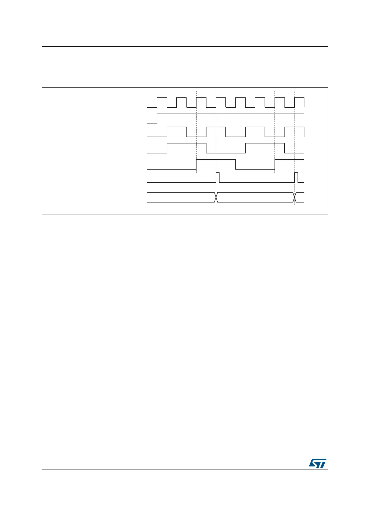
The delay between the rising edge on ETR and the actual clock of the counter is due to the
resynchronization circuit on the ETRP signal.
Figure 182. Control circuit in external clock mode 2
17.3.4 Capture/compare channels
Each Capture/Compare channel is built around a capture/compare register (including a
shadow register), a input stage for capture (with digital filter, multiplexing and prescaler) and
an output stage (with comparator and output control).
The following figure gives an overview of one Capture/Compare channel.
The input stage samples the corresponding TIx input to generate a filtered signal TIxF.
Then, an edge detector with polarity selection generates a signal (TIxFPx) which can be
used as trigger input by the slave mode controller or as the capture command. It is
prescaled before the capture register (ICxPS).
069
&17B(1
(75
(753
(75)
&RXQWHUFORFN &.B,17 &.B36&
&RXQWHUUHJLVWHU
&.B,17