Fast-mode Plus Inter-integrated circuit (FMPI2C) interface RM0390
752/1328 RM0390 Rev 4
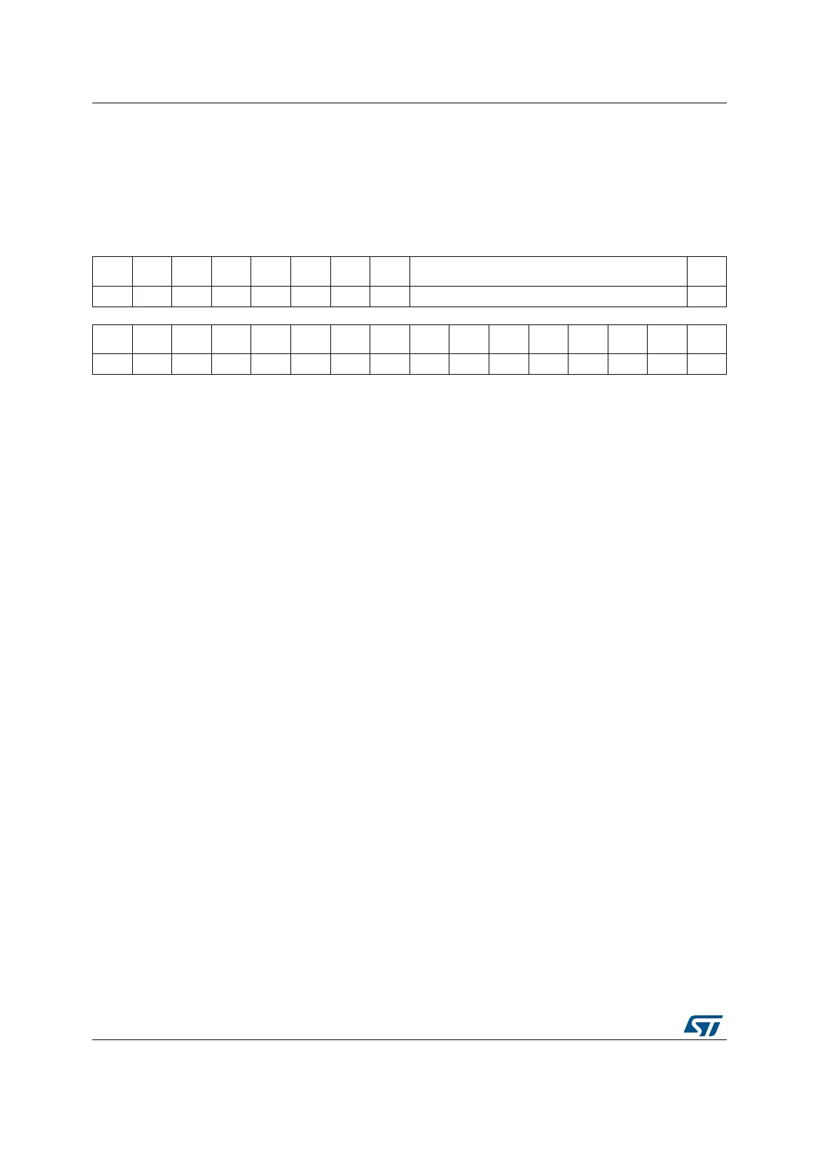
23.7.7 Interrupt and status register (FMPI2C_ISR)
Address offset: 0x18
Reset value: 0x0000 0001
Access: No wait states
31 30 29 28 27 26 25 24 23 22 21 20 19 18 17 16
Res. Res. Res. Res. Res. Res. Res. Res. ADDCODE[6:0] DIR
rr
1514131211109876543210
BUSY Res. ALERT
TIME
OUT
PEC
ERR
OVR ARLO BERR TCR TC STOPF NACKF ADDR RXNE TXIS TXE
r rrrrrrrrrrrrrsrs
Bits 31:24 Reserved, must be kept at reset value.
Bits 23:17 ADDCODE[6:0]: Address match code (Slave mode)
These bits are updated with the received address when an address match event occurs
(ADDR = 1).
In the case of a 10-bit address, ADDCODE provides the 10-bit header followed by the 2 MSBs
of the address.
Bit 16 DIR: Transfer direction (Slave mode)
This flag is updated when an address match event occurs (ADDR=1).
0: Write transfer, slave enters receiver mode.
1: Read transfer, slave enters transmitter mode.
Bit 15 BUSY: Bus busy
This flag indicates that a communication is in progress on the bus. It is set by hardware when a
START condition is detected. It is cleared by hardware when a Stop condition is detected, or
when PE=0.
Bit 14 Reserved, must be kept at reset value.
Bit 13 ALERT: SMBus alert
This flag is set by hardware when SMBHEN=1 (SMBus host configuration), ALERTEN=1 and
a SMBALERT event (falling edge) is detected on SMBA pin. It is cleared by software by setting
the ALERTCF bit.
Note: This bit is cleared by hardware when PE=0.
If the SMBus feature is not supported, this bit is reserved and forced by hardware to ‘0’.
Refer to Section 23.3: FMPI2C implementation.
Bit 12 TIMEOUT: Timeout or t
LOW
detection flag
This flag is set by hardware when a timeout or extended clock timeout occurred. It is cleared
by software by setting the TIMEOUTCF bit.
Note: This bit is cleared by hardware when PE=0.
If the SMBus feature is not supported, this bit is reserved and forced by hardware to ‘0’.
Refer to Section 23.3: FMPI2C implementation.