RM0390 Rev 4 951/1328
RM0390 Serial audio interface (SAI)
973
In reception mode, the MONO bit can be set and is meaningful only if the number of slots is
equal to 2 as in transmitter mode. When it is set, only slot 0 data will be stored in the FIFO.
The data belonging to slot 1 will be discarded since, in this case, it is supposed to be the
same as the previous slot. If the data flow in reception mode is a real stereo audio flow with
a distinct and different left and right data, the MONO bit is meaningless. The conversion
from the output stereo file to the equivalent mono file is done by software.
Companding mode
Telecommunication applications can require to process the data to be transmitted or
received using a data companding algorithm.
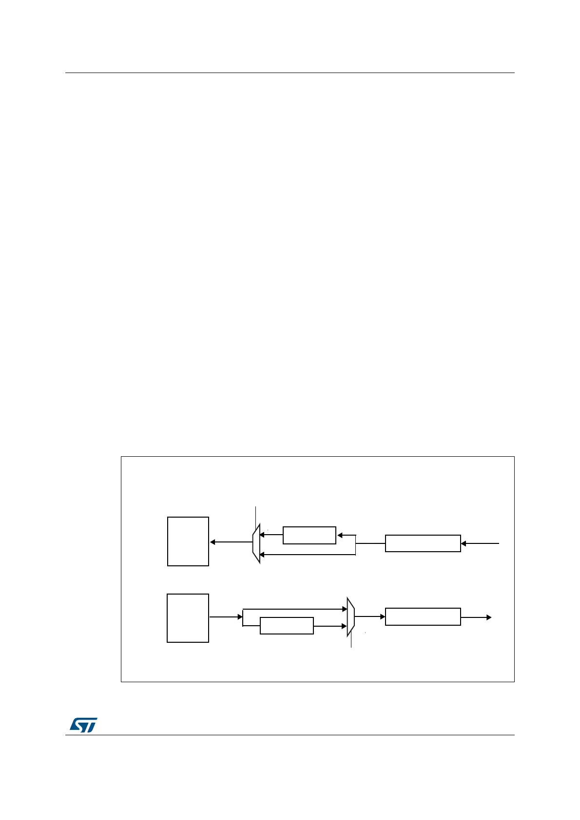
Depending on the COMP[1:0] bits in the SAI_xCR2 register (used only when TDM mode is
selected), the application software can choose to process or not the data before sending it
on SD serial output line (compression) or to expand the data after the reception on SD serial
input line (expansion) as illustrated in Figure 365. The two companding modes supported
are the µ-Law and the A-Law log which are a part of the CCITT G.711 recommendation.
The companding standard used in the United States and Japan is the µ-Law. It supports 14
bits of dynamic range (COMP[1:0] = 10 in the SAI_xCR2 register).
The European companding standard is A-Law and supports 13 bits of dynamic range
(COMP[1:0] = 11 in the SAI_xCR2 register).
Both µ-Law or A-Law companding standard can be computed based on 1’s complement or
2’s complement representation depending on the CPL bit setting in the SAI_xCR2 register.
In µ-Law and A-Law standards, data are coded as 8 bits with MSB alignment. Companded
data are always 8-bit wide. For this reason, DS[2:0] bits in the SAI_xCR1 register will be
forced to 010 when the SAI audio block is enabled (SAIEN bit = 1 in the SAI_xCR1 register)
and when one of these two companding modes selected through the COMP[1:0] bits.
If no companding processing is required, COMP[1:0] bits should be kept clear.
Figure 365. Data companding hardware in an audio block in the SAI
1. Not applicable when AC’97 or SPDIF are selected.
H[SDQG
),)2
&203>@
&203>@
ELWVKLIWUHJLVWHU
6'
5HFHLYHUPRGHELW02'(>@ LQ6$,B[&5
7UDQVPLWWHUPRGHELW02'(>@ LQ6$,B[&5
069
ELWVKLIWUHJLVWHU
6'
FRPSUHVV
),)2
 Loading...


