USB on-the-go full-speed/high-speed (OTG_FS/OTG_HS) RM0390
1260/1328 RM0390 Rev 4
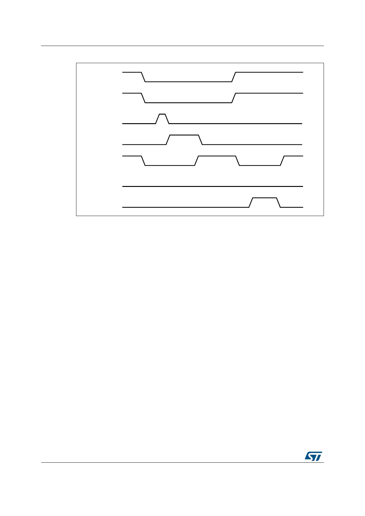
Figure 429. B-device SRP
1. VBUS_VALID = V
BUS
valid signal from PHY
B_VALID = B-peripheral valid session to PHY
DISCHRG_VBUS = discharge signal to PHY
SESS_END = session end signal to PHY
CHRG_VBUS = charge V
BUS
signal to PHY
DP = Data plus line
DM = Data minus line
The following points refer and describe the signal numeration shown in the Figure 429:
1. To save power, the host suspends and turns off port power when the bus is idle.
The OTG_FS/OTG_HS controller sets the early suspend bit in the core interrupt
register after 3 ms of bus idleness. Following this, the OTG_FS/OTG_HS controller
sets the USB suspend bit in the core interrupt register.
The OTG_FS/OTG_HS controller informs the PHY to discharge V
BUS
.
2. The PHY indicates the session’s end to the device. This is the initial condition for SRP.
The OTG_FS/OTG_HS controller requires 2 ms of SE0 before initiating SRP.
For a USB 1.1 full-speed serial transceiver, the application must wait until V
BUS
discharges to 0.2 V after BSVLD (in OTG_GOTGCTL) is deasserted. This discharge
time can be obtained from the transceiver vendor and varies from one transceiver to
another.
3. The OTG_FS/OTG_HS core informs the PHY to speed up V
BUS
discharge.
4. The application initiates SRP by writing the session request bit in the OTG control and
status register. The OTG_FS/OTG_HS controller perform data-line pulsing followed by
V
BUS
pulsing.
5. The host detects SRP from either the data-line or V
BUS
pulsing, and turns on V
BUS
.
The PHY indicates V
BUS
power-on to the device.
6. The OTG_FS/OTG_HS controller performs V
BUS
pulsing.
The host starts a new session by turning on V
BUS
, indicating SRP success. The
OTG_FS/OTG_HS controller interrupts the application by setting the session request
DLF
9%86B9$/,'
%B9$/,'
',6&+5*B9%86
6(66B(1'
'3
'0
&+5*B9%86
6XVSHQG
'DWDOLQHSXOVLQJ &RQQHFW
9
%86
SXOVLQJ
/RZ
 Loading...


