RM0390 Rev 4 375/1328
RM0390 Analog-to-digital converter (ADC)
400
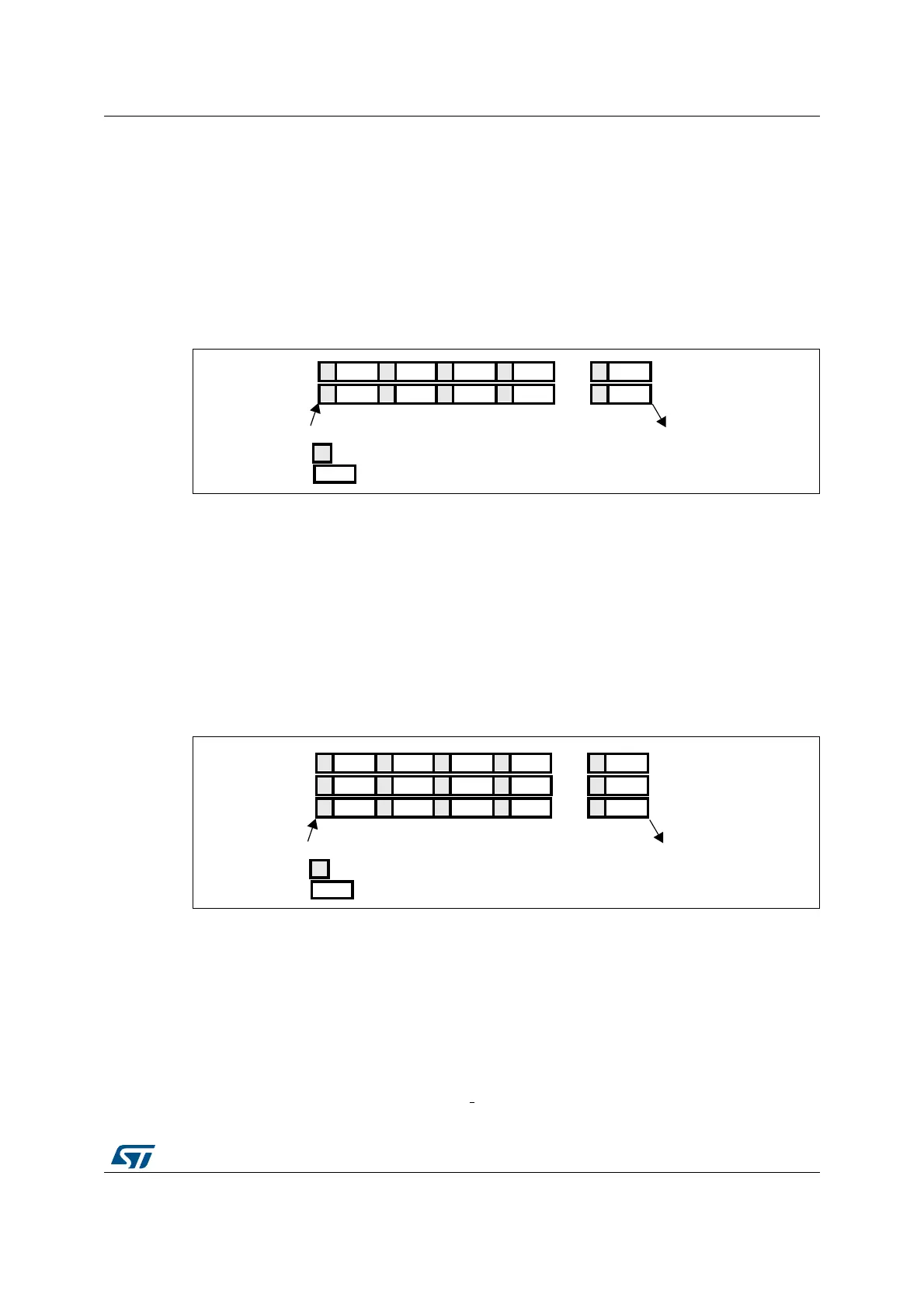
Dual ADC mode
At the end of conversion event on ADC1 or ADC2:
• A 32-bit DMA transfer request is generated (if DMA[1:0] bits in the ADC_CCR register
are equal to 0b10). This request transfers the ADC2 converted data stored in the upper
half-word of the ADC_CDR 32-bit register to the SRAM and then the ADC1 converted
data stored in the lower half-word of ADC_CCR to the SRAM.
• An EOC interrupt is generated (if enabled on one of the two ADC interfaces) when the
ADC1/ADC2’s regular channels have all been converted.
Figure 82. Regular simultaneous mode on 16 channels: dual ADC mode
Triple ADC mode
At the end of conversion event on ADC1, ADC2 or ADC3:
• Three 32-bit DMA transfer requests are generated (if DMA[1:0] bits in the ADC_CCR
register are equal to 0b01). Three transfers then take place from the ADC_CDR 32-bit
register to SRAM: first the ADC1 converted data, then the ADC2 converted data and
finally the ADC3 converted data. The process is repeated for each new three
conversions.
• An EOC interrupt is generated (if enabled on one of the three ADC interfaces) when the
ADC1/ADC2/ADC3’s regular channels are have all been converted.
Figure 83. Regular simultaneous mode on 16 channels: triple ADC mode
13.9.3 Interleaved mode
This mode can be started only on a regular group (usually one channel). The external
trigger source comes from the regular channel multiplexer of ADC1.
Dual ADC mode
After an external trigger occurs:
• ADC1 starts immediately
• ADC2 starts after a delay of several
ADC clock cycles
#( #( #( #(
#( #( #( #(
!$#
!$#
4RIGGER
%NDOFCONVERSIONON!$#AND!$#
#ONVERSION
3AMPLING
#(
#(
AI
#( #( #( #(
#( #( #( #(
!$#
!$#
4RIGGER
%NDOFCONVERSIONON!$#!$#AND!$#
#ONVERSION
3AMPLING
#(
#(
AI
#( #( #( #(
!$#
#(