Analog-to-digital converter (ADC) RM0390
366/1328 RM0390 Rev 4
Figure 76. Right alignment of 12-bit data
Figure 77. Left alignment of 12-bit data
Special case: when left-aligned, the data are aligned on a half-word basis except when the
resolution is set to 6-bit. in that case, the data are aligned on a byte basis as shown in
Figure 78.
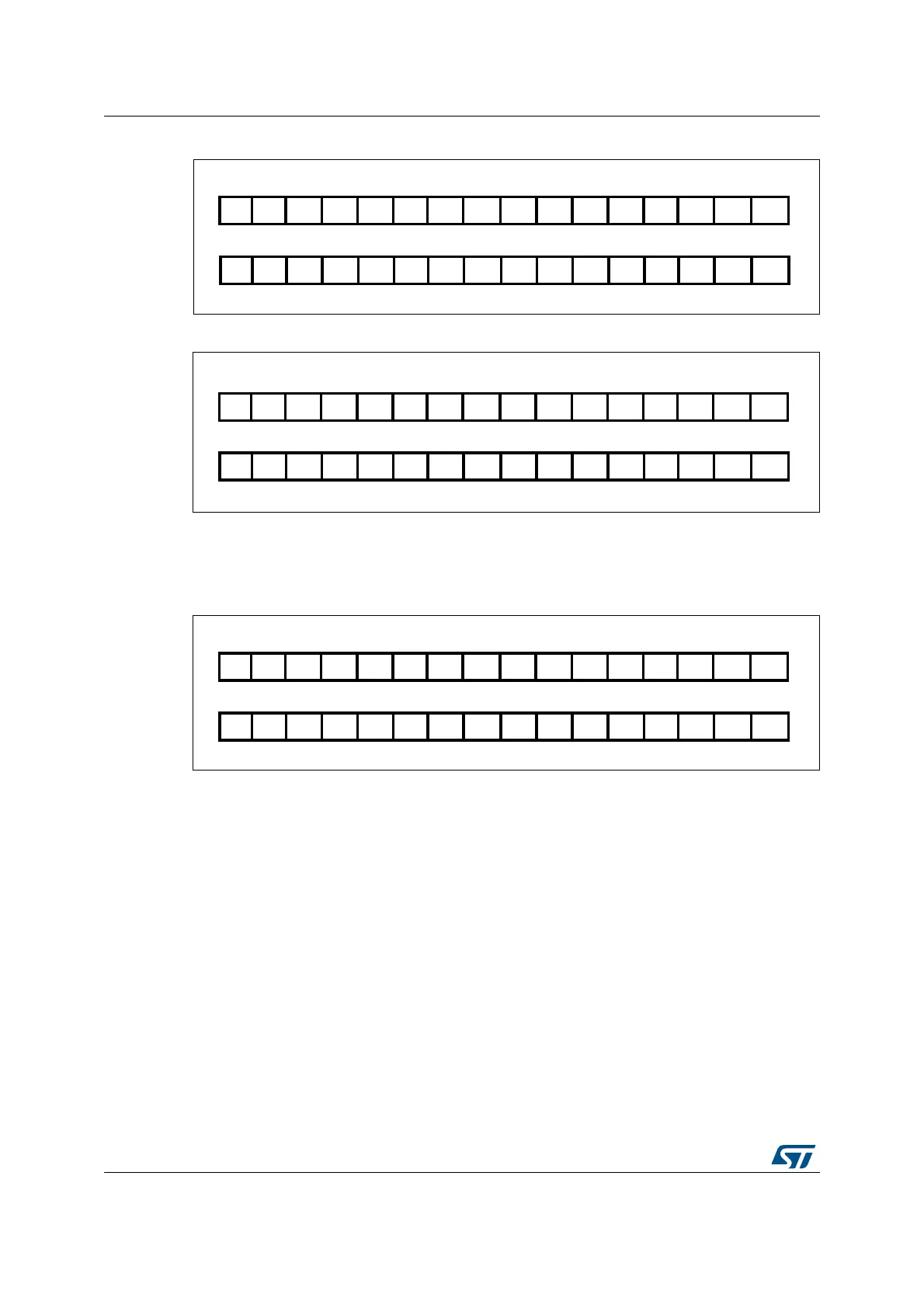
Figure 78. Left alignment of 6-bit data
13.5 Channel-wise programmable sampling time
The ADC samples the input voltage for a number of ADCCLK cycles that can be modified
using the SMP[2:0] bits in the ADC_SMPR1 and ADC_SMPR2 registers. Each channel can
be sampled with a different sampling time.
The total conversion time is calculated as follows:
T
conv
= Sampling time + 12 cycles
Example:
With ADCCLK = 30 MHz and sampling time = 3 cycles:
T
conv
= 3 + 12 = 15 cycles = 0.5 µs with APB2 at 60 MHz
$$$ $ $ $ $ $ $ $$$3%843%843%843%84
$$
$$
)NJECTEDGROUP
2EGULARGROUP
$ $ $ $ $ $ $ $
AI
$$
$ $ $ $ $ $$$$$3%84
)NJECTEDGROUP
2EGULARGROUP
AI
$ $ $ $ $ $ $ $ $ $ $ $
$$
3%843%843%843%843%843%84
)NJECTEDGROUP
2EGULARGROUP
AI
$ $ $ $ $ $
3%843%84 $ $ $ $ 3%84