Advanced-control timers (TIM1&TIM8) RM0390
470/1328 RM0390 Rev 4
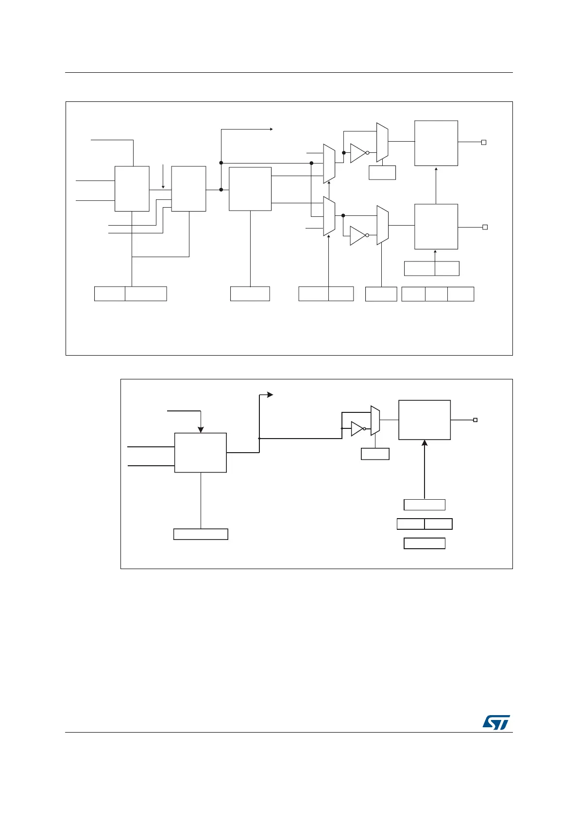
Figure 138. Output stage of capture/compare channel (channels 1 to 3)
Figure 139. Output stage of capture/compare channel (channel 4)
The capture/compare block is made of one preload register and one shadow register. Write
and read always access the preload register.
In capture mode, captures are actually done in the shadow register, which is copied into the
preload register.
In compare mode, the content of the preload register is copied into the shadow register
which is compared to the counter.
069
2XWSXW
PRGH
FRQWUROOHU
&17!&&5
&17 &&5
7,0B&&05
2&0>@
2&5()
2&&(
'HDGWLPH
JHQHUDWRU
2&B'7
2&1B'7
'7*>@
7,0B%'75
µ
µ
&&(
7,0B&&(5
&&1(
&&3
7,0B&&(5
&&13
7,0B&&(5
2&
2XWSXW
HQDEOH
FLUFXLW
2&1
&&(
7,0B&&(5
&&1(
266,
7,0B%'75
02( 2665
[
[
2XWSXW
VHOHFWRU
2&[5()
2&5()&
7RWKHPDVWHUPRGH
FRQWUROOHU
2XWSXW
HQDEOH
FLUFXLW
2&5()
(75)
069
2XWSXW
PRGH
FRQWUROOHU
7,0B&&05
2&0>@
2&5()
&&3
7,0B&&(5
2&
7RWKHPDVWHU
PRGHFRQWUROOHU
2XWSXW
HQDEOH
FLUFXLW
(75
&17!&&5
&17!&&5
7,0B&&(5
7,0B%'75
7,0B&5
266,02(
&&(
2,6
 Loading...


