Reset and clock control (RCC) RM0390
120/1328 RM0390 Rev 4
The RCC feeds the external clock of the Cortex System Timer (SysTick) with the AHB clock
(HCLK) divided by 8. The SysTick can work either with this clock or with the Cortex clock
(HCLK), configurable in the SysTick control and status register.
FCLK acts as Cortex
®
-M4 with FPU free-running clock. For more details, refer to the
Cortex
®
-M4 with FPU technical reference manual.
6.2.1 HSE clock
The high speed external clock signal (HSE) can be generated from two possible clock
sources:
• HSE external crystal/ceramic resonator
• HSE external user clock
The resonator and the load capacitors have to be placed as close as possible to the
oscillator pins in order to minimize output distortion and startup stabilization time. The
loading capacitance values must be adjusted according to the selected oscillator.
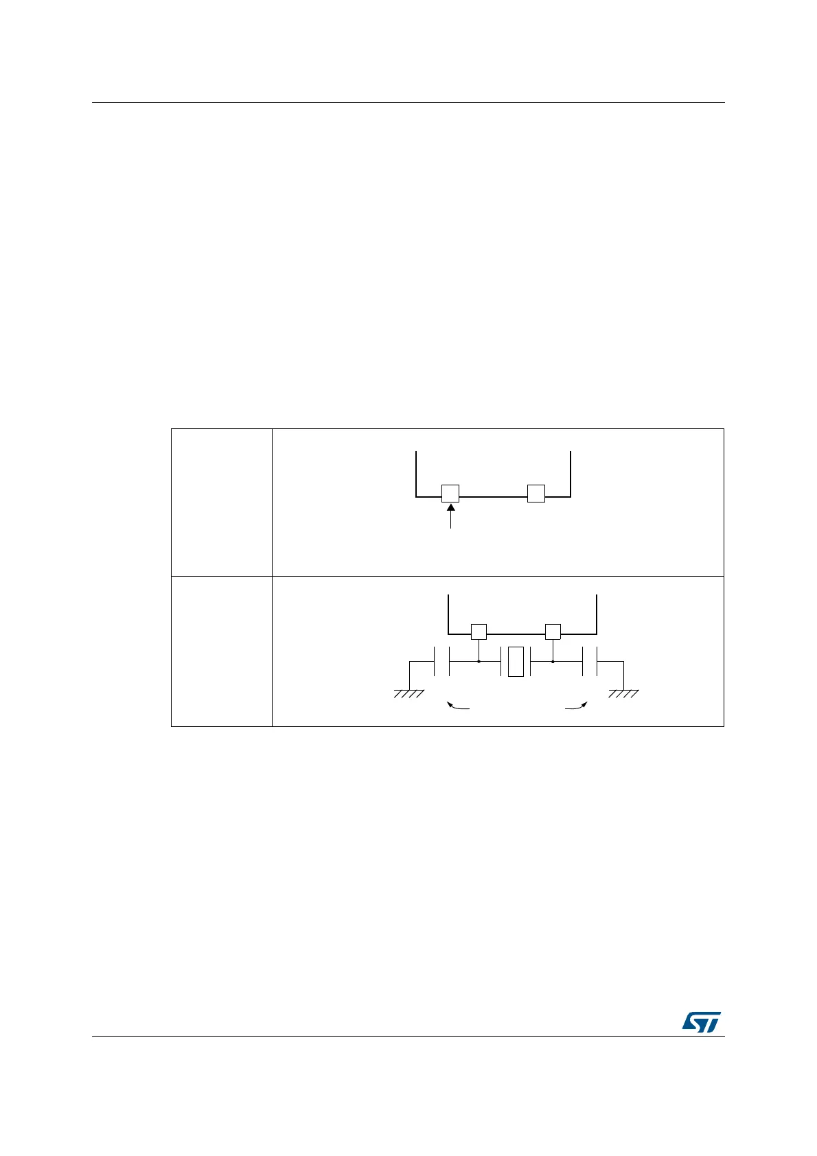
External source (HSE bypass)
In this mode, an external clock source must be provided. You select this mode by setting the
HSEBYP and HSEON
bits in the RCC clock control register (RCC_CR). The external clock
signal (square, sinus or triangle) with ~50% duty cycle has to drive the OSC_IN pin while the
OSC_OUT pin should be left HI-Z. See Figure 15.
External crystal/ceramic resonator (HSE crystal)
The HSE has the advantage of producing a very accurate rate on the main clock.
The associated hardware configuration is shown in Figure 15. Refer to the electrical
characteristics section of the datasheet for more details.
The HSERDY flag in the RCC clock control register (RCC_CR) indicates if the high-speed
external oscillator is stable or not. At startup, the clock is not released until this bit is set by
Figure 15. HSE/ LSE clock sources (hardware configuration)
External clock
Crystal/ceramic
resonators
OSC_OUT
External
source
(HI-Z)
OSC_IN OSC_OUT
Load
capacitors
C
L2
C
L1
 Loading...


