General-purpose timers (TIM2 to TIM5) RM0390
556/1328 RM0390 Rev 4
counts until we write ‘0 to the CEN bit in the TIM2_CR1 register. Both counter clock
frequencies are divided by 3 by the prescaler compared to CK_INT (f
CK_CNT
= f
CK_INT
/3).
• Configure Timer 1 master mode to send its Update Event (UEV) as trigger output
(MMS=010 in the TIM1_CR2 register).
• Configure the Timer 1 period (TIM1_ARR registers).
• Configure Timer 2 to get the input trigger from Timer 1 (TS=000 in the TIM2_SMCR
register).
• Configure Timer 2 in trigger mode (SMS=110 in TIM2_SMCR register).
• Start Timer 1 by writing ‘1 in the CEN bit (TIM1_CR1 register).
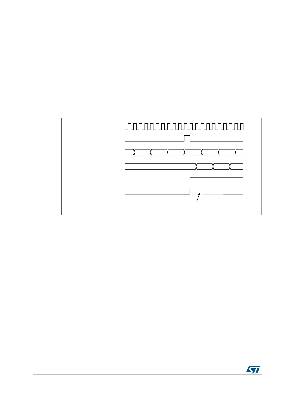
Figure 201. Triggering timer 2 with update of timer 1
As in the previous example, you can initialize both counters before starting counting.
Figure 202 shows the behavior with the same configuration as in Figure 199, but in trigger
mode instead of gated mode (SMS=110 in the TIM2_SMCR register).
069
:ULWH7,)
&.B,17
7,0(5&17
)'
7,0(5&17
7,0(5&(1 &17B(1
7,0(57,)
)( ))
7,0(58(9
 Loading...


