RM0390 Rev 4 315/1328
RM0390 Flexible memory controller (FMC)
324
Power-down mode
This mode is selected by setting the MODE bits to ‘110’ and by configuring the Target Bank
bits (CTB1 and/or CTB2) in the FMC_SDCMR register.
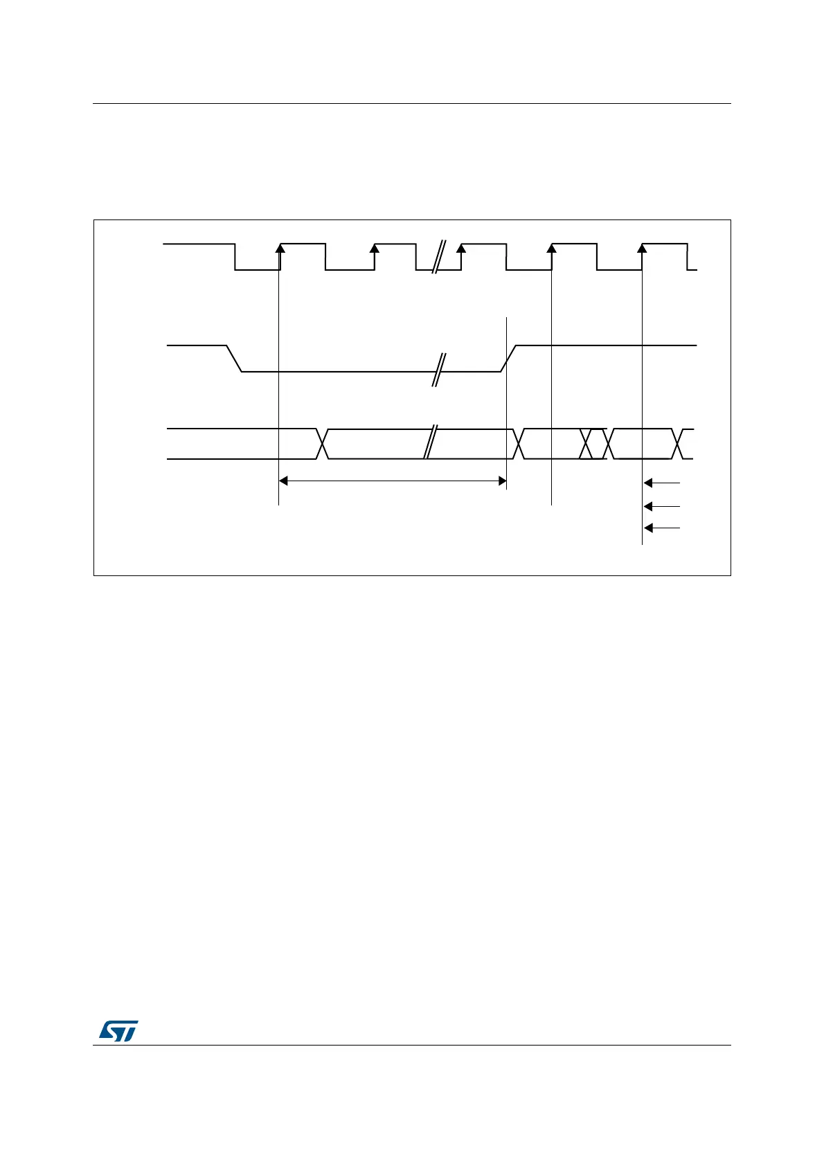
Figure 60. Power-down mode
If the Write data FIFO is not empty, all data are sent to the memory before activating the
Power-down mode.
As soon as an SDRAM device is selected, the SDRAM controller exits from the Power-down
mode. After the memory access, the selected SDRAM device remains in Normal mode.
During Power-down mode, all SDRAM device input and output buffers are deactivated
except for the SDCKE which remains low.
The SDRAM device cannot remain in Power-down mode longer than the refresh period and
cannot perform the Auto-refresh cycles by itself. Therefore, the SDRAM controller carries
out the refresh operation by executing the operations below:
1. Exit from Power-down mode and drive the SDCKE high
2. Generate the PALL command only if a row was active during Power-down mode
3. Generate the auto-refresh command
4. Drive SDCKE low again to return to Power-down mode.
To exit from Power-down mode, the MODE bits must be set to ‘000’ (Normal mode) and the
Target Bank bits (CTB1 and/or CTB2) must be configured in the FMC_SDCMR register.
11.7.5 SDRAM controller registers
SDRAM Control registers 1,2 (FMC_SDCR1,2)
Address offset: 0x140+ 4* (x – 1), x = 1,2
3$#,+
3$#+%
#/--!.$
./0
./0 !#4)6%
)NPUTBUFFERSGATEDOFF!LLBANKSIDLE
%NTER0OWERDOWN %XIT0OWERDOWN
T2#$
T2!3
T2#
-36
 Loading...


