RM0390 Rev 4 921/1328
RM0390 SPDIF receiver interface (SPDIFRX)
929
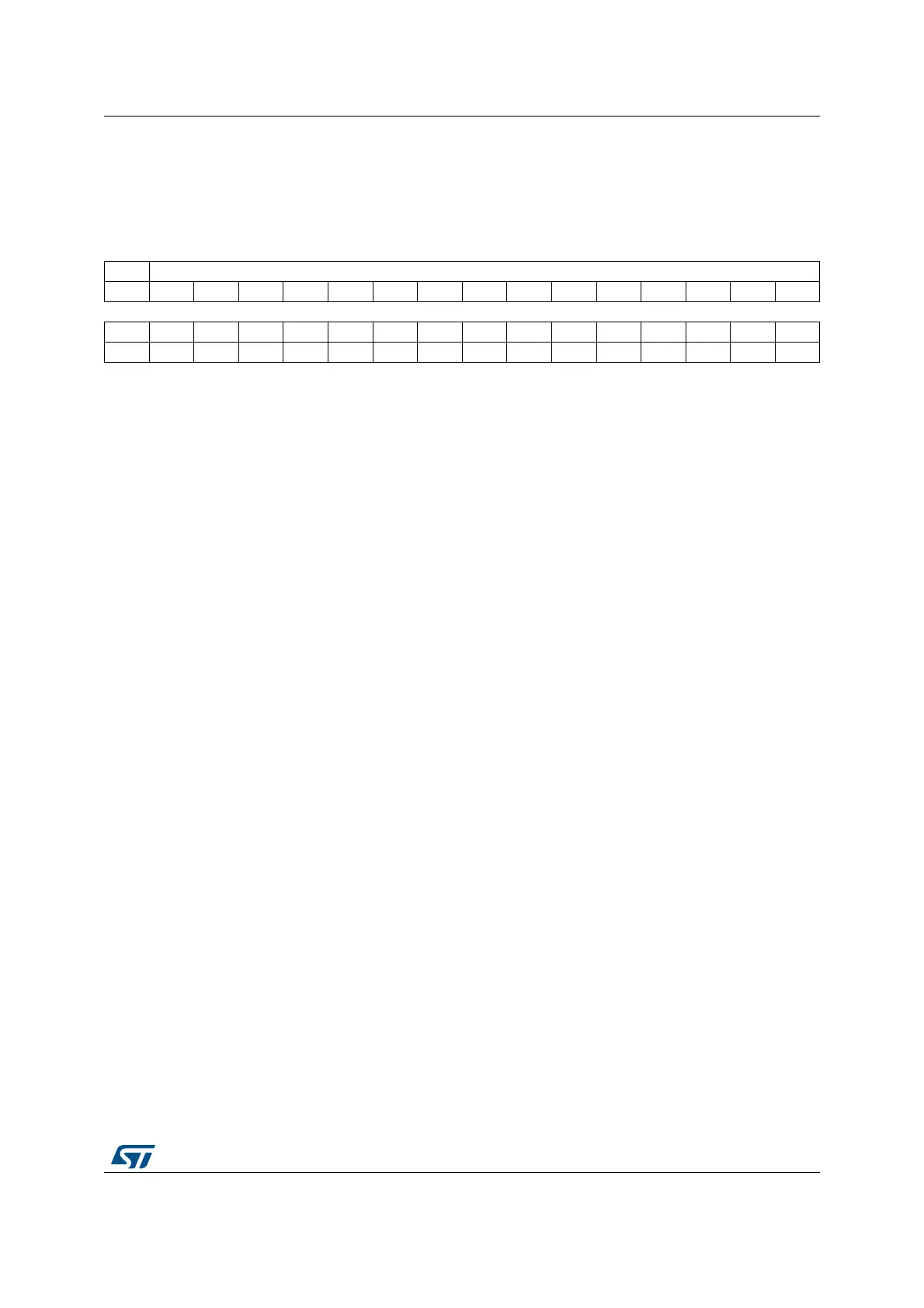
27.5.3 Status register (SPDIFRX_SR)
Address offset: 0x08
Reset value: 0x0000 0000
31 30 29 28 27 26 25 24 23 22 21 20 19 18 17 16
Res. WIDTH5[14:0]
rrrrrrrrrrrrrrr
1514131211109876543210
Res. Res. Res. Res. Res. Res. Res. TERR SERR FERR SYNCD SBD OVR PERR CSRNE RXNE
rrrrrrrrr
Bit 31 Reserved, must be kept at reset value.
Bits 30:16 WIDTH5[14:0]: Duration of 5 symbols counted with SPDIFRX_CLK
This value represents the amount of SPDIFRX_CLK clock periods contained on a length of 5
consecutive symbols. This value can be used to estimate the S/PDIF symbol rate. Its accuracy is
limited by the frequency of SPDIFRX_CLK.
For example if the SPDIFRX_CLK is fixed to 84 MHz, and WIDTH5 = 147d. The estimated sampling
rate of the S/PDIF stream is:
Fs = 5 x F
SPDIFRX_CLK
/ (WIDTH5 x 64) ~ 44.6 kHz, so the closest standard sampling rate is 44.1
kHz.
Note that WIDTH5 is updated by the hardware when SYNCD goes high, and then every frame.
Bits 15:9 Reserved, must be kept at reset value.
Bit 8 TERR: Time-out error
This bit is set by hardware when the counter TRCNT reaches its max value. It indicates that the time
interval between two transitions is too long. It generally indicates that there is no valid signal on
SPDIFRX_IN input.
This flag is cleared by writing SPDIFRXEN to 0
An interrupt is generated if IFEIE=1 in the SPDIFRX_IMR register
0: No sequence error is detected
1: Sequence error is detected
Bit 7 SERR: Synchronization error
This bit is set by hardware when the synchronization fails due to amount of re-tries for NBTR.
This flag is cleared by writing SPDIFRXEN to 0
An interrupt is generated if IFEIE=1 in the SPDIFRX_IMR register.
0: No synchronization error is detected
1: Synchronization error is detected
Bit 6 FERR: Framing error
This bit is set by hardware when an error occurs during data reception: preamble not at the
expected place, short transition not grouped by pairs...
This is set by the hardware only if the synchronization has been completed (SYNCD = 1).
This flag is cleared by writing SPDIFRXEN to 0
An interrupt is generated if IFEIE=1 in the SPDIFRX_IMR register.
0: no Manchester Violation detected
1: Manchester Violation detected
 Loading...


