Real-time clock (RTC) RM0390
654/1328 RM0390 Rev 4
– 0.95 ppm accuracy, obtained in a calibration window of several seconds
• Timestamp function for event saving (1 event)
• Tamper detection:
– 2 tamper events with configurable filter and internal pull-up.
• 20 backup registers (80 bytes). The backup registers are reset when a tamper
detection event occurs.
• Alternate function output (RTC_OUT) which selects one of the following two outputs:
– RTC_CALIB: 512 Hz or 1 Hz clock output (with an LSE frequency of 32.768 kHz).
This output is enabled by setting the COE bit in the RTC_CR register. It is routed
to the device RTC_AF1 function.
– RTC_ALARM (Alarm A, Alarm B or wakeup).
This output is selected by configuring the OSEL[1:0] bits in the RTC_CR register.
It is routed to the device RTC_AF1 function.
• RTC alternate function inputs:
– RTC_TS: timestamp event detection. It is routed to the device RTC_AF1 and
RTC_AF2 functions.
– RTC_TAMP1: TAMPER1 event detection. It is routed to the device RTC_AF1 and
RTC_AF2 functions.
– RTC_TAMP2: TAMPER2 event detection.
– RTC_REFIN: reference clock input (usually the mains, 50 or 60 Hz).
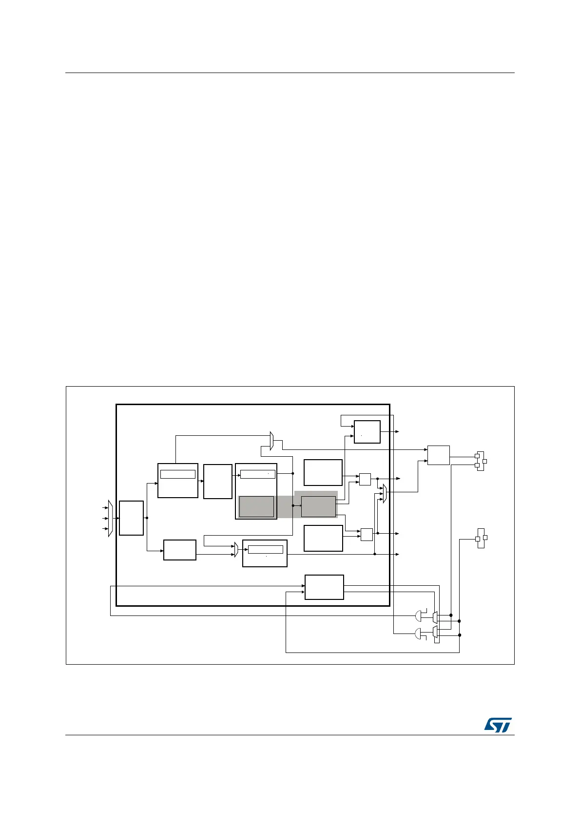
Figure 240. RTC block diagram
1. On STM32F446xx devices, the RTC_AF1 and RTC_AF2 additional function are connected to PC13 and PA0, respectively.
-36
CK?APRE
DEFAULT(Z
CK SPRE
DEFAULT(Z
24#?#!,)"
(Z
24#?7542
24##,+
754&
(3%?24#
-(ZMAX
,3%(Z
,3)
!SYN CH
BITPRESCALER
DEFAULT
3YNCHRONOUS
BITPRESCALER
DEFAULT
#ALENDAR
BITWAKEUP
AUTORELOADTIMER
!LARM!
24#?!,2-!2
REGISTERS
!,2!&
24#?!,!2-
24#?02%2 24#?02%2
3HADOWREGISTERS
24#?42
24#?$2
#OARSE
#ALIBRATION
24#?#!,)"2
!,2"&
4IMESTAMP
REGISTE RS
43&
/UTPUT
CONTROL
24#?!&
24#?/54
(Z
24#?!,2-!332
!LARM"
24#?!,2-"2
REGISTERS
24#?!,2-"332
3MOOTH
CALIBRATION
24#?#!,2
0RESCALER
75#+3%,;=
"ACKUPAND
24#TAMPER
CONTROLREGISTERS
24#?4!-0
24#?43
4!-0%
43%
24#?!&
3HADOWREGISTER
24#?332
24#?4!-0
 Loading...


