Chapter 11 Replacing the Motherboard and Associated Components 11-3
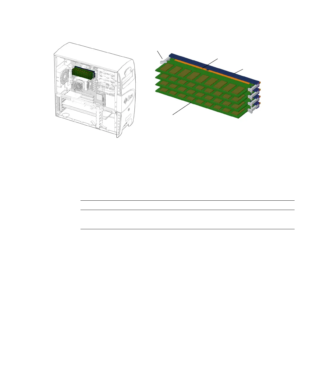
FIGURE 11-1 DIMM Location and Identification
Depending upon the configuration of your workstation, you can either add or
replace memory. In either case, the new DIMMs must meet the Sun workstation
requirements.
TABLE 11-1 lists the acceptable DIMM pair configurations.
See the Sun Blade 1500 Product Notes, 817-5131, for more information about memory
configurations and conditions.
If you are not removing an existing DIMM, proceed to “Installing DIMMs” on
page 11-7.
11.1.2 Removing DIMMs
1. Power off the system, open and position the chassis.
Refer to:
■ “Powering Off the Workstation” on page 10-4
■ “Removing the Access Panel” on page 10-12
■ “Positioning the Chassis” on page 10-16
TABLE 11-1 DIMM Pair Configurations
DIMM Pair Total Memory Installed DIMM Pairs Configuration
1 GB memory 2 x 512 MB DIMMs Standard
2 GB memory 2 x 1 GB DIMMs Optional
DIMM
DIMM0
DIMM1
DIMM2
DIMM3
DIMM gold edge
DIMM ejector levers (8)
DIMM slots (4)