Chapter 11 Replacing the Motherboard and Associated Components 11-19
2. Identify the CPU fan and heat sink assembly location on the motherboard.
The CPU fan and heat sink assembly centers within the locking ring which
surrounds the CPU.
3. (Optional) If the DIMM cooling duct is blocking access to install the CPU fan and
heat sink assembly, refer to
Step 3 of “Removing DIMMs” on page 11-3.
4. Remove the CPU fan and heat sink assembly and clips from the packaging.
5. Clean the top surface of the CPU with an appropriate cleaner so that it is smooth.
6. Remove any covers or shields protecting the thermal pad of the replacement CPU
fan and heat sink assembly.
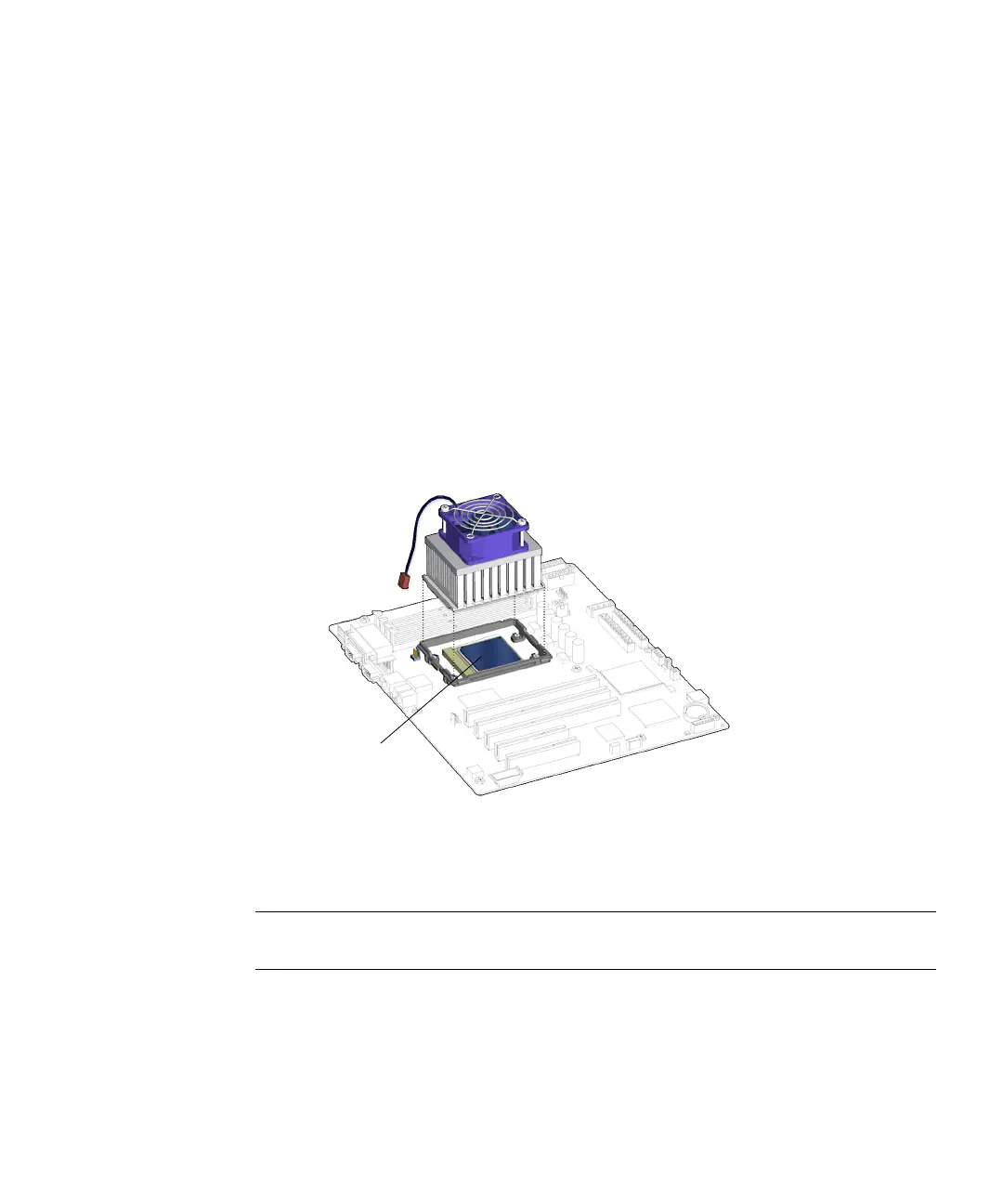
7. Arrange the CPU fan and heat sink assembly over the CPU so that the cable is
toward the rear of the chassis.
See FIGURE 11-20.
FIGURE 11-20 Setting the CPU Fan and Heat Sink Assembly on the CPU
8. Attach the CPU fan and heat sink assembly clips onto the locking ring.
Note – To prevent the heat sink from tilting out of the locking ring, maintain a
consistent downward force to the heat sink while attaching the clips.
a. Align the clip over the CPU locking ring.
See FIGURE 11-21.
CPU