Chapter 11 Replacing the Motherboard and Associated Components 11-45
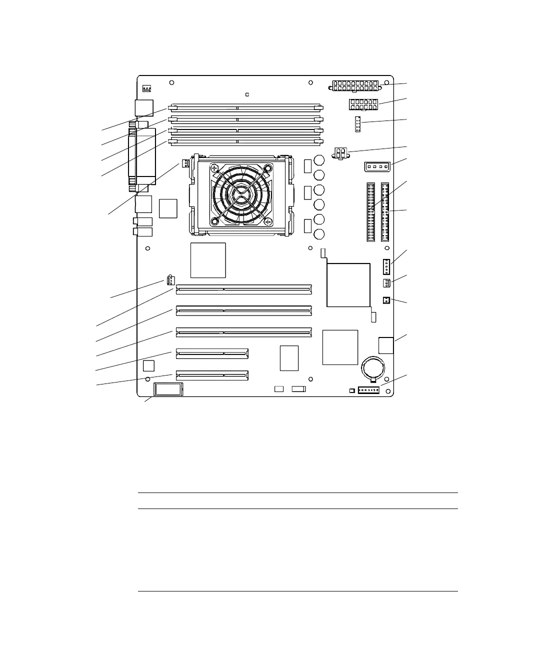
FIGURE 11-43 Motherboard Connector Layout
TABLE 11-7 lists the motherboard connectors and their functions.
TABLE 11-7 Motherboard Connectors and Descriptions
Location Description
DIMM0 - DIMM3 DDR 132 pin memory slots
FAN0 SYS Front fan connection
FAN1 SYS Rear fan connection
FAN2 CPU fan connection
IDE PRI Primary IDE connection
Power supply (PS2)
Power supply (PS1)
IDE power (IDE PWR)
Smart card reader
(SCR0)
Optical drive
Hard drive (IDE PRI)
(IDE SEC)
Power button
Front fan (FAN0 SYS)
Speaker (SPK0)
Audio (J13 AUDIO)
USB (J19 USB)
Rear fan
(FAN1 SYS)
PCI4
PCI3
PCI2
PCI1
PCI0
DIMM3
DIMM2
DIMM1
DIMM0
Power supply (PS0)
CPU fan
(FAN2)
(J24 SW0)
NVRAM (NVRAM0)