Chapter 14 Replacing Internal Cables 14-9
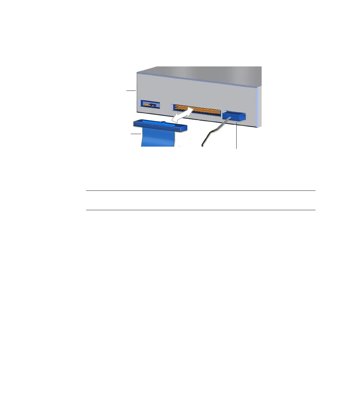
3. Connect the interface cable into the optical drive interface connector.
See FIGURE 14-7.
FIGURE 14-7 Connecting the Interface Cable to the Optical Drive
4. Route the interface cable through the chassis.
Note – The interface cable is a flat cable and can be bent to fit. Use caution not to
fold the cable too much as it can be damaged.
5. Connect the interface cable into the motherboard at IDE SEC.
See FIGURE 14-1 and FIGURE 14-5.
6. Inspect the cabling to verify that:
■ The interface cable is secure in the optical drive connector.
■ The interface cable is secure in the motherboard connector IDE SEC.
7. Install the access panel, power on the system, and verify the optical drive
interface cable installation.
Refer to:
■ “Installing the Access Panel” on page 15-5
■ “Powering On the Workstation” on page 15-8
■ “Verifying an Installation” on page 15-11
Interface cable
IDE power cable
Optical
drive