Appendix B Signal Descriptions B-13
TABLE B-17 lists the pinouts for connector J19 USB.
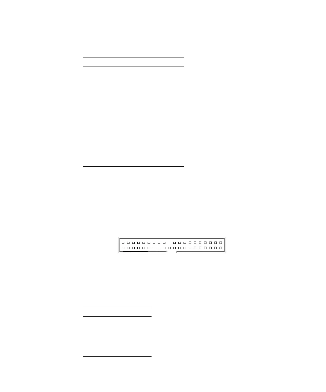
B.2.4 IDE Interface Connectors
The two IDE interface connectors, IDE PRI and IDE SEC have similar pinouts.
FIGURE B-10 identifies the IDE interface connector.
FIGURE B-10 IDE Interface Connector
The connector pinouts are described in TABLE B-18.
TABLE B-17 Front USB Connector J19 USB Pinouts
Pin Signal
1 Data -, left USB port
2 Data +, left USB port
3 Ground
4 Ground
5 Data +, right USB port
6 Data -, right USB port
7 Ground
8 +5 V, right USB port
9 +5 V, left USB port
10 Shield
TABLE B-18 IDE Interface Connectors IDE PRI and IDE SEC Pinouts
Pin Signal
1 HDRST#
2 Ground
3 D7
4 D8
1
2
39
40