Chapter 11 Replacing the Motherboard and Associated Components 11-15
■ “Removing the Access Panel” on page 10-12
2. Locate the CPU fan and heat sink assembly.
See FIGURE 11-14.
3. (Optional) If the DIMM cooling duct and rear fan are blocking access to the CPU
fan and heat sink assembly clip, remove them.
Refer to:
■ “Removing the DIMM Cooling Duct” on page 13-23.
■ “Removing the Rear Fan” on page 13-16.
4. Position the chassis.
Refer to “Positioning the Chassis” on page 10-16.
5. If you have not already removed it, lift the DIMM cooling duct out of the way.
Refer to Step 3 of “Removing DIMMs” on page 11-3.
6. Disconnect the CPU fan and heat sink assembly cable from the motherboard
connector, FAN2.
See FIGURE 11-15.
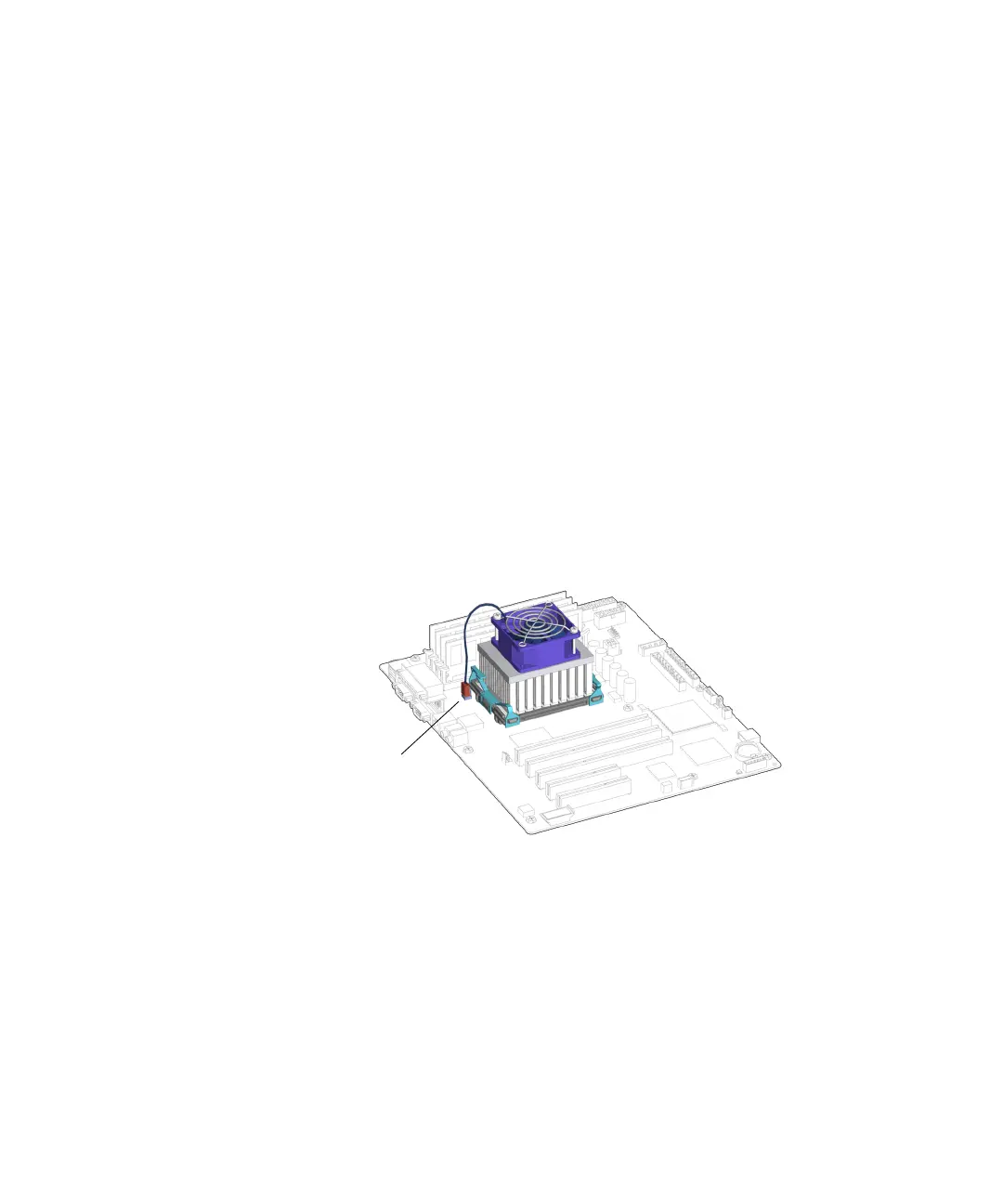
FIGURE 11-15 Disconnecting the CPU Fan and Heat Sink Assembly Cable
7. Release the CPU fan and heat sink assembly clips.
a. Press down on the latch of the clip, unhooking that end of the clip from the
locking ring end tab.
See FIGURE 11-16.
Connector FAN2