11-56 Sun Blade 1500 Service, Diagnostics, and Troubleshooting Manual • December 2004
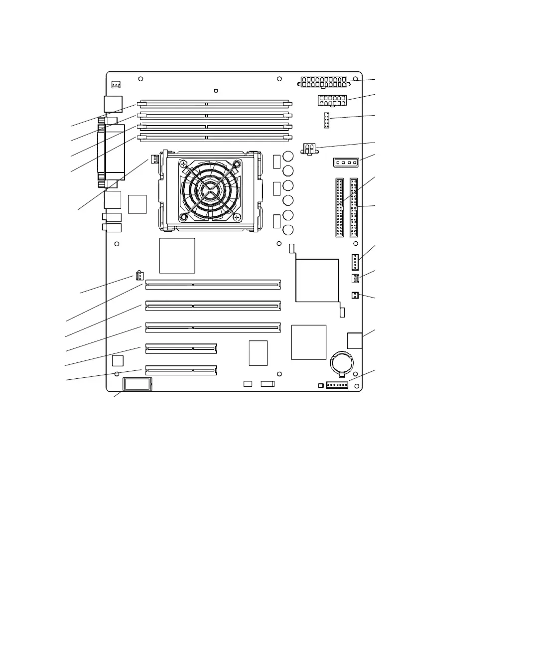
FIGURE 11-51 Motherboard Connectors
12. Connect the power and signal cables to the corresponding component connector:
■ Power supply cables at connectors PS0, PS1, and PS2
■ IDE power at connector IDE PWR
■ Power button at connector J24 SW0
■ Front fan at connector FAN0 SYS
■ Rear fan at connector FAN1 SYS (if the rear fan was not removed)
■ Front audio at connector J13 AUDIO
■ Speaker at connector SPK0
13. Secure the cables into the cable clips.
See FIGURE 11-52.
Power supply (PS2)
Power supply (PS1)
IDE power (IDE PWR)
Smart card reader
(SCR0)
Optical drive
Hard drive (IDE PRI)
(IDE SEC)
Power button
Front fan (FAN0 SYS)
Speaker (SPK0)
Audio (J13 AUDIO)
USB (J19 USB)
Rear fan
(FAN1 SYS)
PCI4
PCI3
PCI2
PCI1
PCI0
DIMM3
DIMM2
DIMM1
DIMM0
Power supply (PS0)
CPU fan
(FAN2)
(J24 SW0)
NVRAM (NVRAM0)