Chapter 11 Replacing the Motherboard and Associated Components 11-21
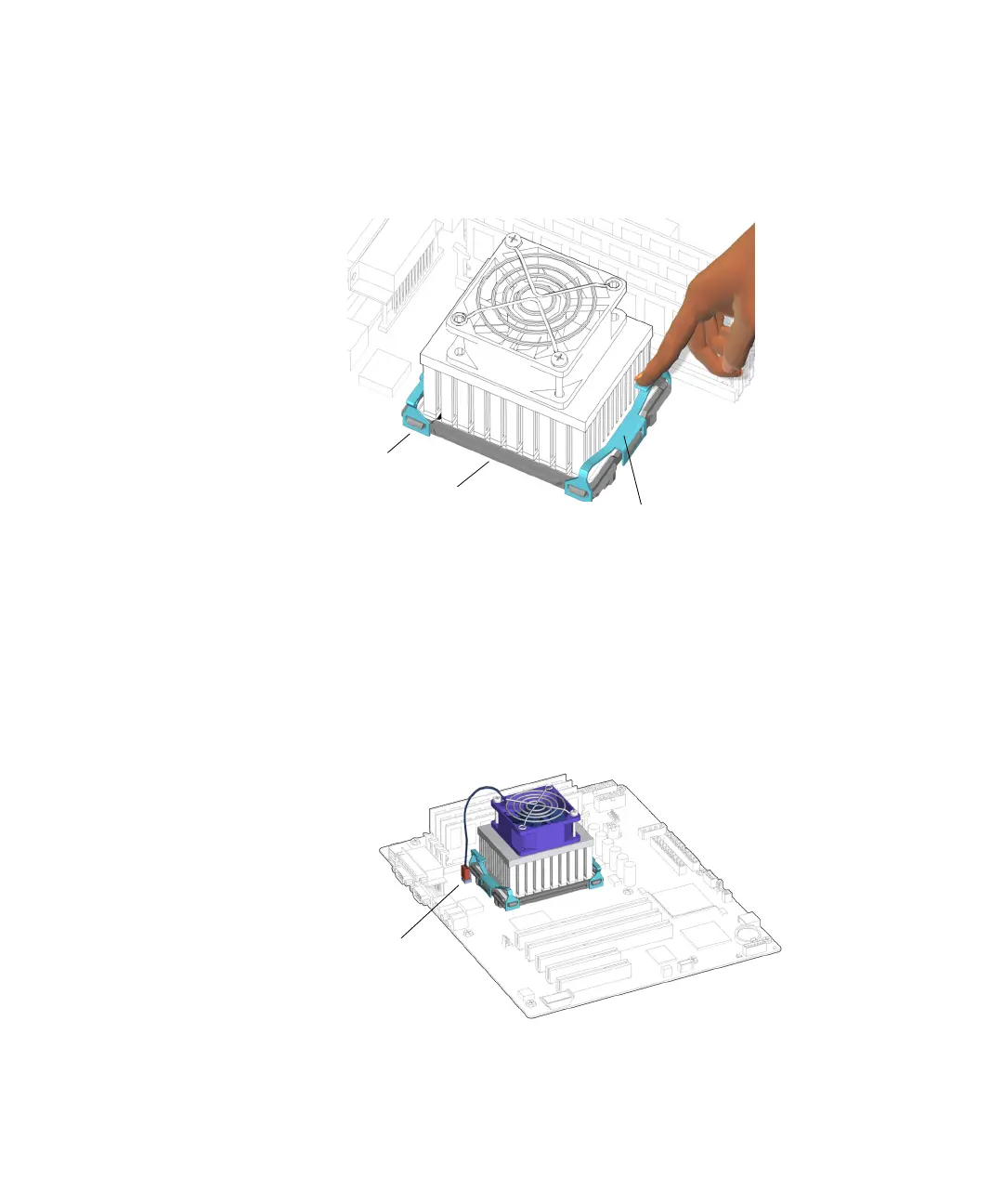
d. Press down on the opposite end of the clip, hooking it over the end tab, and
securing it to the locking ring.
See FIGURE 11-23.
FIGURE 11-23 Securing the Clip to the Locking Ring
The clip clicks into place. If installed separately, repeat from Step a for the other
clip.
9. Attach the CPU fan and heat sink assembly cable to the FAN2 connector on the
motherboard.
See FIGURE 11-24. Press until it is snug.
FIGURE 11-24 Connecting the CPU Fan and Heat Sink Assembly Cable
End tabs (4)
Clips (2)
Locking ring
Connector FAN2