11-14 Sun Blade 1500 Service, Diagnostics, and Troubleshooting Manual • December 2004
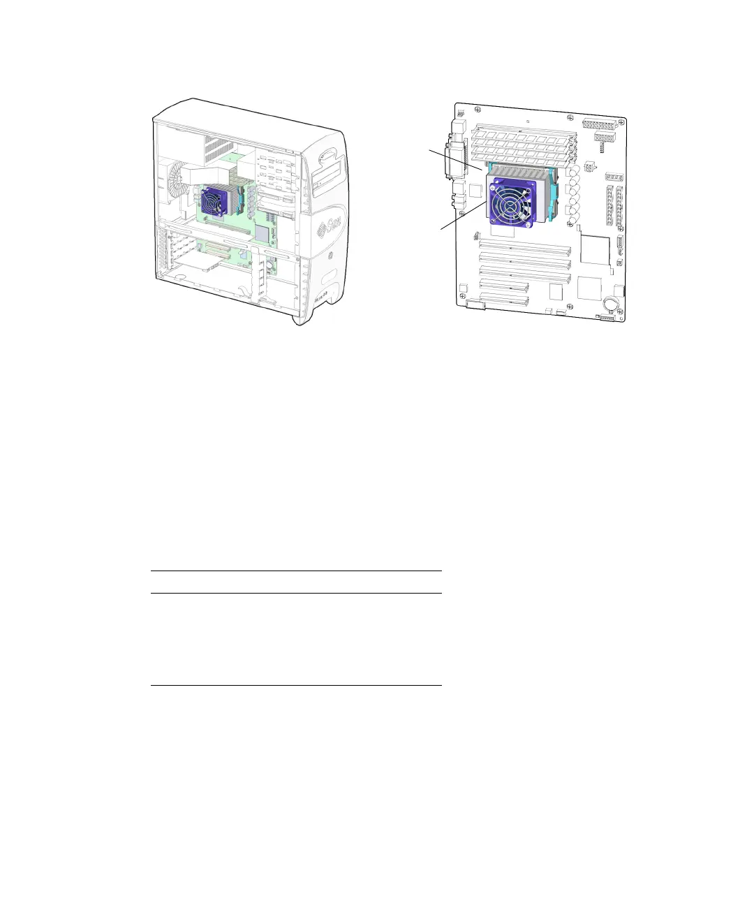
FIGURE 11-14 CPU Fan and Heat Sink Assembly Location and Identification
The CPU fan and heat sink assembly is fastened to the CPU with two clips. These
spring-loaded clips latch to the locking ring which surrounds the CPU and apply a
downward force, pressing the CPU fan and heat sink assembly against the CPU.
When the clips are removed or installed one at a time, they have a tendency to rock
the CPU fan and heat sink assembly. To prevent the CPU fan and heat sink assembly
from rocking, either hold the assembly steady or remove and install both clips at the
same time.
TABLE 11-3 lists the CPU fan specifications.
11.2.2 Removing the CPU Fan and Heat Sink Assembly
1. Power off the system and open the chassis.
Refer to:
■ “Powering Off the Workstation” on page 10-4
TABLE 11-3 CPU Fan Specifications
Specification Value (Maximum)
Voltage 13.8 VDC
Current 0.24 AMPS
Speed 5400 RPM
Flow Rate 27.72 CFM (0.785 m
3
/min)
Connector
FAN2
CPU fan and
heat sink