14-18 Sun Blade 1500 Service, Diagnostics, and Troubleshooting Manual • December 2004
14.5.1 Identifying the Power Switch Assembly
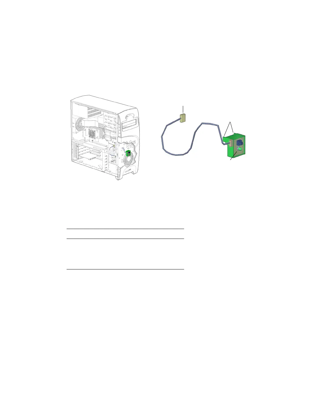
The power switch assembly signals the workstation to power up or power down. It
has a single LED light to indicate power-on status. Signal and power is provided
through a cable connected to the motherboard at J24 SW0.
FIGURE 14-16 shows the
location of and identifies the power switch assembly.
FIGURE 14-16 Power Switch Assembly Location and Identification
TABLE 14-1 lists the power switch assembly specifications.
14.5.2 Removing the Power Switch Assembly
1. Power off the system, open the chassis, and remove the bezel.
Refer to:
■ “Powering Off the Workstation” on page 10-4
■ “Removing the Access Panel” on page 10-12
■ “Removing the Bezel” on page 10-14
TABLE 14-1 Power Switch Assembly Specifications
Specification Value
Voltage 1-20 Volts
Current 5 Amps
Type SPST intermittent
Connector J24 SW0
Tabs (4)
Power switch LED