Appendix B Signal Descriptions B-11
More information about attaching a stereoscopic imager is available in the Sun XVR-
600 Graphics Accelerator Installation and User’s Guide, 817-2195 or the Sun XVR-1200
Graphics Accelerator Installation and User’s Guide, 816-7386.
B.2 Internal Connectors
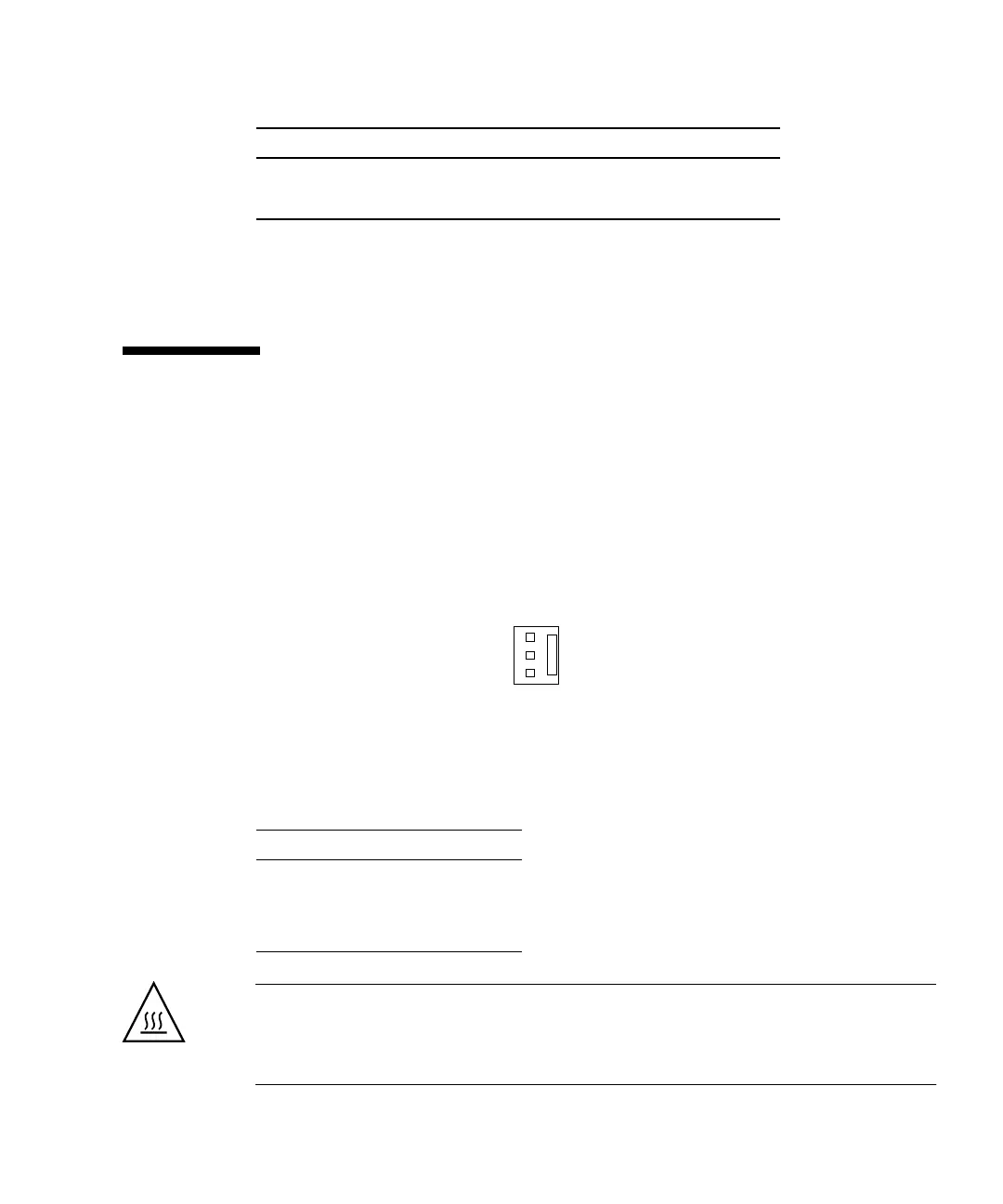
B.2.1 Fan Connectors
The three fan connectors, FAN0 SYS, FAN1 SYS, and FAN2, have the same pinouts.
FIGURE B-7 identifies these fan connectors.
FIGURE B-7 Fan Connector
TABLE B-15 lists these signals.
Caution – Though the connectors have the same pinouts, they are not
interchangeable. Do not connect the CPU fan cable to connector FAN1 SYS.
Similarly, do not connect the rear fan cable to FAN2. Transposing the cables may
result in system overheating and CPU failure.
8 Ground
9 Done input
TABLE B-15 Fan Connectors FAN0 SYS, FAN1 SYS, and FAN2 Pinouts
Pin Signal
1 Ground
2 8 - 12 V
3 Tachometer Signal
TABLE B-14 DB-9 In Stereoscopic Imager Interface Connector Pinouts (Continued)
Pin Signal
3
2
1