Chapter 11 Replacing the Motherboard and Associated Components 11-13
This message means that each of the two DIMMs in the lower slots comes from a
different manufacturer. The system still uses the DIMMs.
This message means that each of the two DIMMs in the upper slots has a different
internal memory layout. The system does not use the DIMMs.
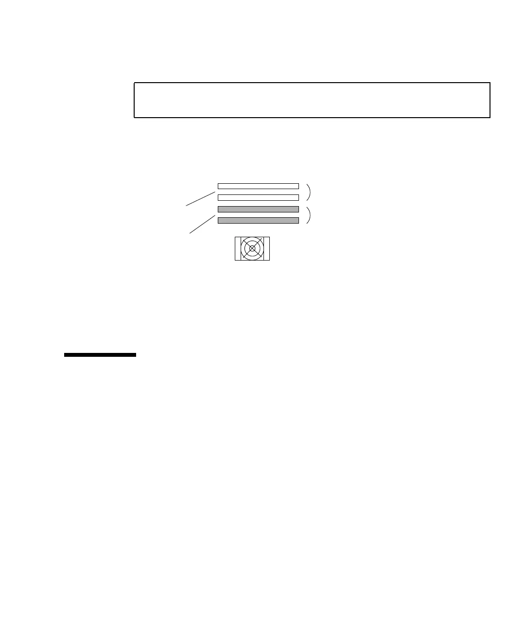
FIGURE 11-13 identifies the location of the faulty DIMMs in the previous examples.
FIGURE 11-13 Examples of Faulty DIMM Locations
A system must have at least one functional pair of DIMMs to display a message. A
system with more than one pair of DIMMs might display more than one message.
11.2 Replacing the CPU Fan and Heat Sink
Assembly
This section describes removal and installation of the CPU fan and heat sink
assembly. Topics include:
■ “Identifying the CPU Fan and Heat Sink Assembly” on page 11-13
■ “Removing the CPU Fan and Heat Sink Assembly” on page 11-14
■ “Installing the CPU Fan and Heat Sink Assembly” on page 11-18
11.2.1 Identifying the CPU Fan and Heat Sink Assembly
The CPU fan and CPU heat sink are attached to each other. Replacing a fan requires
replacing the heat sink as well.
FIGURE 11-14 shows the location and identifies the
CPU fan and heat sink assembly.
NOTICE - CPU0 Bank2 DIMMs have different architectures and will
not be used.
Bank0
Bank2
CPU0
Memory from
different
vendors.
Memory with
different
architecture.