14-22 Sun Blade 1500 Service, Diagnostics, and Troubleshooting Manual • December 2004
5. Connect the cable to the motherboard at J24 SW0.
See FIGURE 14-19 and FIGURE 14-20.
6. Hook the two lower feet of the power switch assembly into the third and fourth
holes in the second row of the front fan grille.
7. Rock the power switch assembly back to snap the two upper feet and tabs into the
four holes.
Make sure the power switch assembly is fully seated against the chassis front panel.
See
FIGURE 14-19.
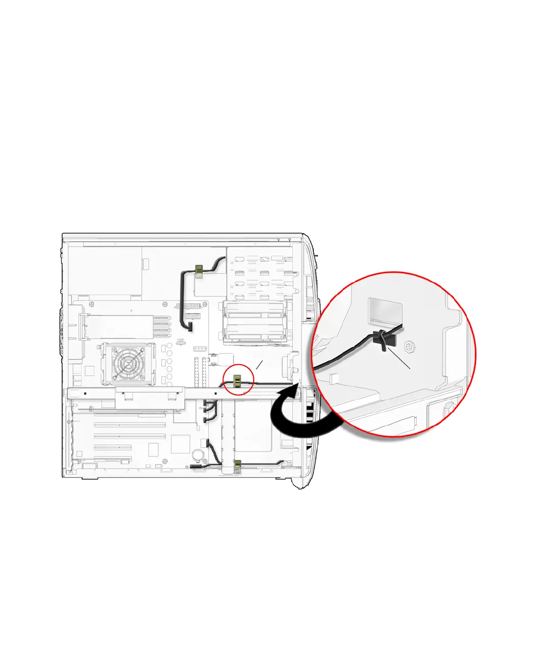
8. Secure the power switch assembly cable to the metal clamp and bezel cable clip.
See FIGURE 14-20.
FIGURE 14-20 Securing the Power Switch Assembly Cable to the Bezel Cable Clip and
Metal Clamp
9. Check that the power switch assembly bracket feet are well seated in the chassis.
10. Inspect the power switch assembly cabling to verify that:
■ The power switch assembly cable is firmly connected to the motherboard
at J24 SW0.
J24 SW0
Metal clamp
Bezel cable clip