11-48 Sun Blade 1500 Service, Diagnostics, and Troubleshooting Manual • December 2004
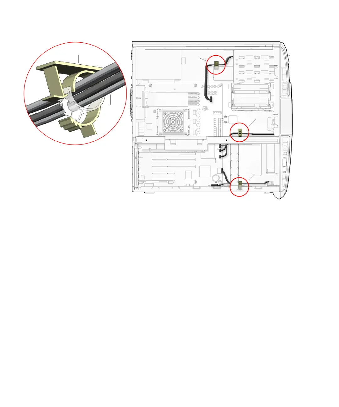
FIGURE 11-44 Removing Cables From the Clips
9. Disconnect the following power and signal cables from the corresponding
motherboard connectors and set them out of the way of the motherboard.
See FIGURE 11-43.
■ Power supply cables at connectors PS0, PS1, and PS2
■ IDE power at connector IDE PWR
■ Power button at connector J24 SW0
■ Front fan at connector FAN0 SYS
■ Rear fan at connector FAN1 SYS (if the rear fan was not removed)
■ Front audio at connector J13 AUDIO
■ Speaker at connector SPK0
10. Disconnect the following interface cables from the corresponding motherboard
connectors and set them out of the way of the motherboard.
See FIGURE 11-43.
■ Smart card reader at connector SCR0
■ Hard drive at connector IDE PRI
■ Optical drive at connector IDE SEC
■ Front USB at connector J19 USB
Routing clip
Power
supply
cables
SCR0
J13 Audio
J19 USB
J24 SW0
FAN0 SYS
SPK0
I/O cable clip
Reader cable clip
Bezel cable clip