CMS32L051 User Manual |Chapter 5 Universal Timer Unit (Timer4)
www.mcu.com.cn 149 / 703
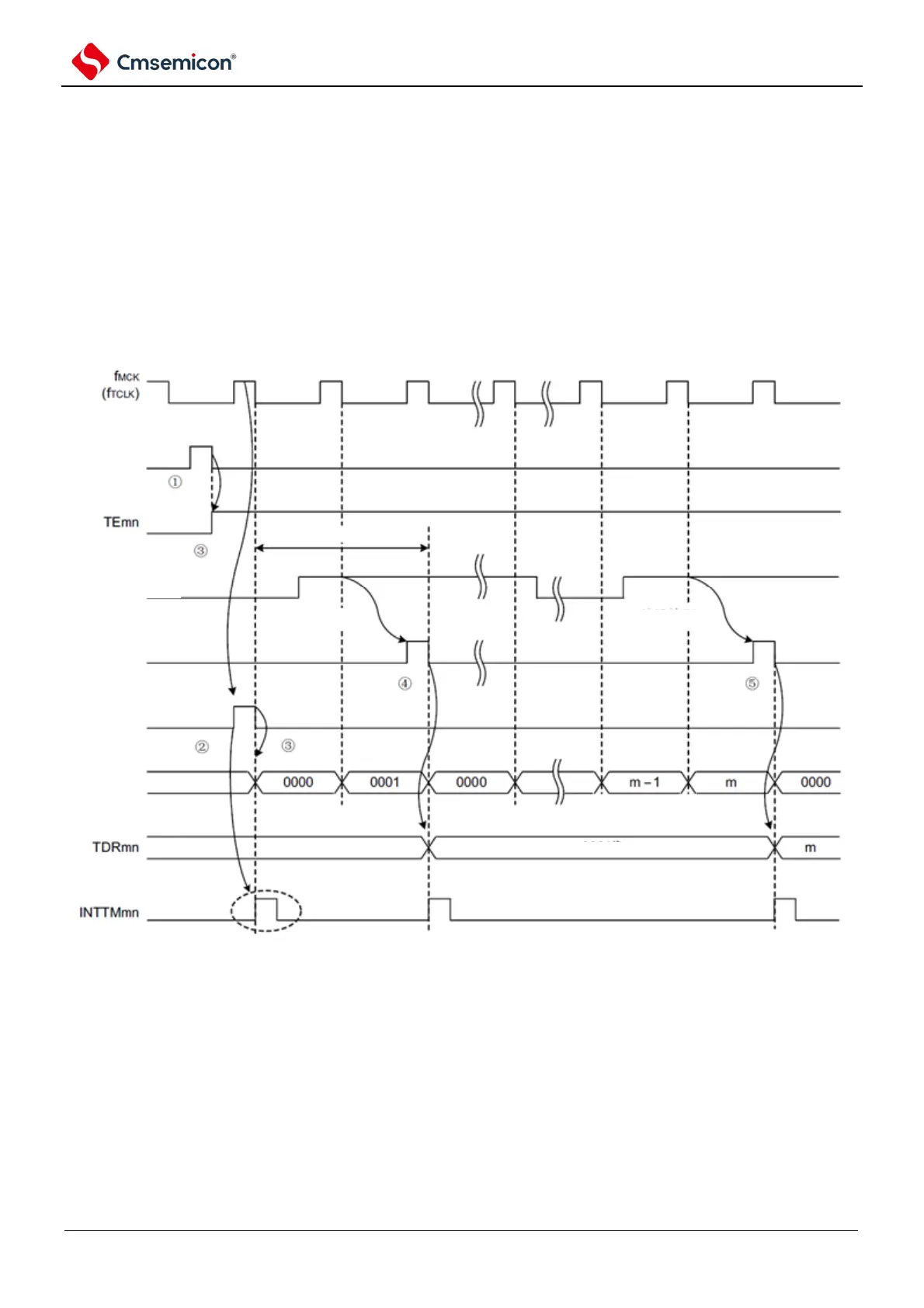
(3) Operation of capture mode (interval measurement of input pulses)
(1) Enter the operating enabled state (TEmn=1) by writing 1 to the TSmn bit.
(2) The timer count register mn (TCRmn) maintains the initial value until the count clock is generated.
(3) Generate a start trigger signal by allowing the first counting clock (fMCK) after operation. Then,
0000H is loaded into the TCRmn register and counts start in capture mode (when MDmn0 bits are
1, INTTMmn is generated by the start trigger signal).
(4) If a valid edge of the TImn input is detected, the value of the TCRmn register is captured to the
TDRmn register, and an INTTMmn interrupt is generated. The snap value at this point is
meaningless. The TCRmn register continues counting starting at 0000H.
(5) If a valid edge of the next TImn input is detected, the value of the TCRmn register is snapped to the
TDRmn register and an INTTMmn interrupt is generated.
Figure 5-28 Operation timing (capture mode: interval measurement of input pulses)
Note: When the clock is entered into TImn (with trigger) before starting, the count is started by detecting the trigger even if
no edge is detected, so the capture value at the time of the 1st capture (4) is not the pulse interval (in this
example, 0001: 2 clock intervals) and must be ignored.
Notice: Because the first count clock cycle runs after the TSmn bit is written and delays the start of the count before the
count clock is generated, an error of up to 1 clock cycle is generated. In addition, if you need information about
the start counting timing, set MDmn0 at 1 so that an interrupt can occur when the count starts.
Remark This is the timing when no noise filter is used. If a noise filter is used, edge detection is delayed by 2 more f
MCK
cycles from the TImn input (3~4 cycles in total). The 1-cycle error is due to the fact that the TImn input is out of sync with
the count clock (f
MCK
).