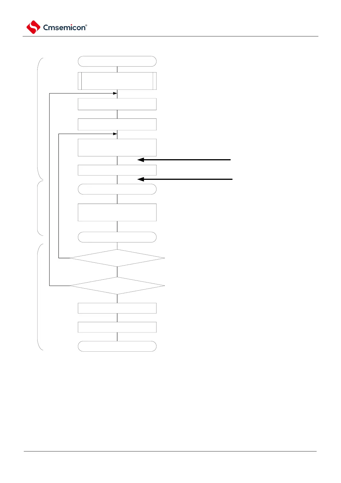
SSPI communication starts
configure transmit and receive
data
enable interrupt
write transmit data into
SIOp(=SDRmn[7:0])
wait for transmitting and reception
completes.
relevant initial configuration, refer to diagram 19-93
(select transmission completion interrupt)
regarding transmit and receive data, configure storage
region and data count (via software, any specified
internal RAM storage region, transmit data pointer
communnication data count)
after clear interrupt request flag(Ifxx) and
release interrupt mask(MKxx), enable
interrupt
start communication via clock
provided by master device.
SCI initial configuration
transmission completion interrupt
RETURN
transmit and receive next data?
disable interrupt (mask).
set STmn bit to 1.
communication completed.
No
Yes
main program
interrupt process program
main program
if interrupt generated via
transmission completion, jump to
interrupt process program.
update communication data count, confirm
whether there is next transmit and receive
data.
read transmit data from buffer and write into
SIOp, update transmit data pointer
Transmit and receive completed?
No
Yes
read received data into
SIOp(=SDRmn[7:0])
read receiving data and write into storage
region, update receive data pointer