EasyManua.ls Logo

Cmsemicon CMS32L051 - Page 557

Default Icon
703 pages
Print Icon
To Next Page IconTo Next Page
To Previous Page IconTo Previous Page
Loading...
V1.2.2
CMS32L051 User Manual |Chapter 14 Serial interface IICA
www.mcu.com.cn 557 / 703
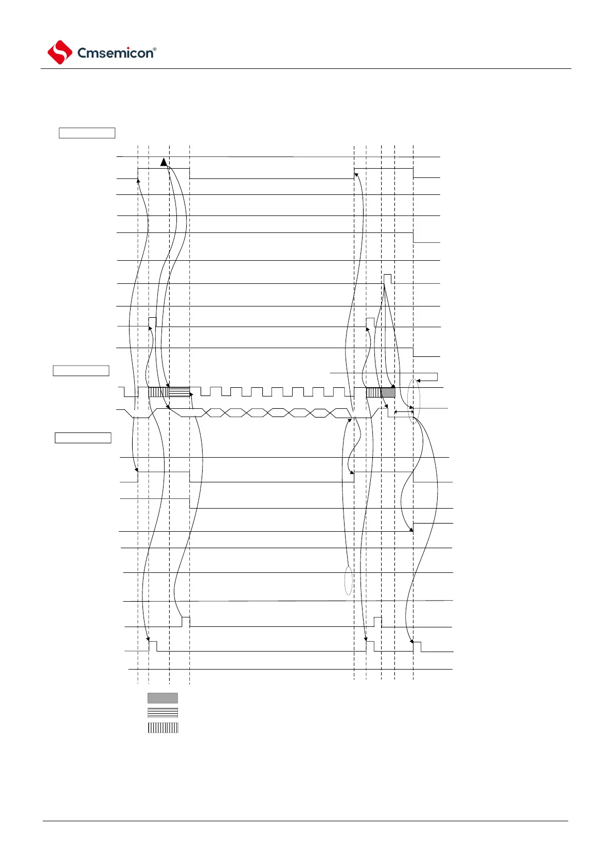
Figure 14-31 Communication example of a master device slave device
(Master device: select 9 clocks of waiting, slave device: select 9 clocks of waiting) (3/4)
(3)
Data~Data~Stop condition
󰪴
note3
󰪲
󰪰
󰪱
master control
IICAn
ACKDn
ACK
detection
WTIMn
(8 or 9 clock cycles
waiting)
H
ACKEn
ACK
control
MSTSn
communicdat
ion state
STTn
ST trigger
H
SPTn
SP trigger
WRELn
release from
wait
L
INTIICAn
interrupt
TRCn
transmit
/reception
bus
SCLAn(bus)
Clock line
SDAAn(bus)
data line
slave
IICAn
ACKDn
ACK
detection
STDn
ST
detection
SPDn
SP
detection
WTIMn
(8 or 9 clock cycles
waiting)
ACKEn
(ACK control)
MSTSn
communicdat
ion state
WRELn
release from
wait
INTIICAn
interrupt
TRCn
transmit
/reception
H
H
L
L
note1
slave device waits
master device and slave device wait
L
D166 D165
D164
ACK
D163
D162 D161
D160
note3
󰪳
ACK
D150
note 2
stop condition
master device waits
D167
Note 1 To release the master from waiting during transmit, you must write data to the IICAn instead of setting the WRELn
bit.
2. The time from the SCLAn pin signal to the generation of the stop condition after the stop condition is issued is at
least 4.0 u s when set to standard mode and at least 0.6us when set to fast mode.
3. To release the wait during the slave receive, the IICAn must be set to "FFH" or set the WRELn bit.

Table of Contents

Related product manuals