CMS32L051 User Manual |Chapter 4 Clock Generation Circuit
www.mcu.com.cn 92 / 703
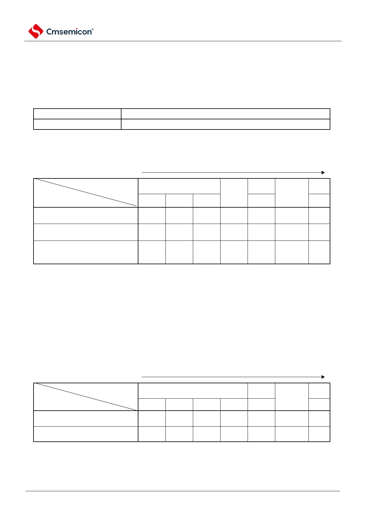
Examples of CPU clock transfer and SFR register settings are shown in Table 4-3.
Table 4-3 Example of CPU transfering and SFR register setting (1/5)
(1) After the reset is released (A), the CPU is transferred to the high-speed internal oscillator clock to run
(B).
Setting of the SFR register
There is no need to set the SFR register (the initial state after the reset is released).
(2) After the reset is released (A), the CPU is transferred to the high-speed system clock to run (C).
(The CPU runs with a high-speed internal oscillator clock (B) immediately after the reset is released.)
(Order of setting SFR registers).
The setting flag of the
SFR register
State transition
(A) (B) (C)
(X1 clock
X
(A) (B) (C)
(X1Clock:10MHz<f
X
)
(A) (B) (C)
(External Master Clock)
No
confirmation
is required
Note 1 After the reset is released, only one clock operation mode control register (CMC) can be written through the 8-bit
memory operation command.
2. The following settings must be made for the oscillation settling time of the Oscillation Settling Time Selection
Register (OSTS).
time set by the OSTS register
Note that the clock must be set after the supply voltage reaches the set clock operable voltage (referring to
the electrical characteristics of the data sheet).
(3) After the reset is released (A), the CPU is transferred to the secondary system clock to run (D).
(The CPU runs with a high-speed internal oscillator clock (B) immediately after the reset is released.)
(Order of setting SFR registers).
The setting flag of the SFR register
State transition
Oscillation
stabilizes
wait
(A) (B) (D)
(XT1 clock).
(A) (B) (D)
(External Subclock)
Note that after the reset is released, only one clock operation mode control register (CMC) can be written through the 8-
bit memory operation command.
Note 1 ×: Ignore
2.Table 4-3(A)~(I) corresponding to fig Figure 4-17(A)~(I).