CMS32L051 User Manual |Chapter 4 Clock Generation Circuit
www.mcu.com.cn 93 / 703
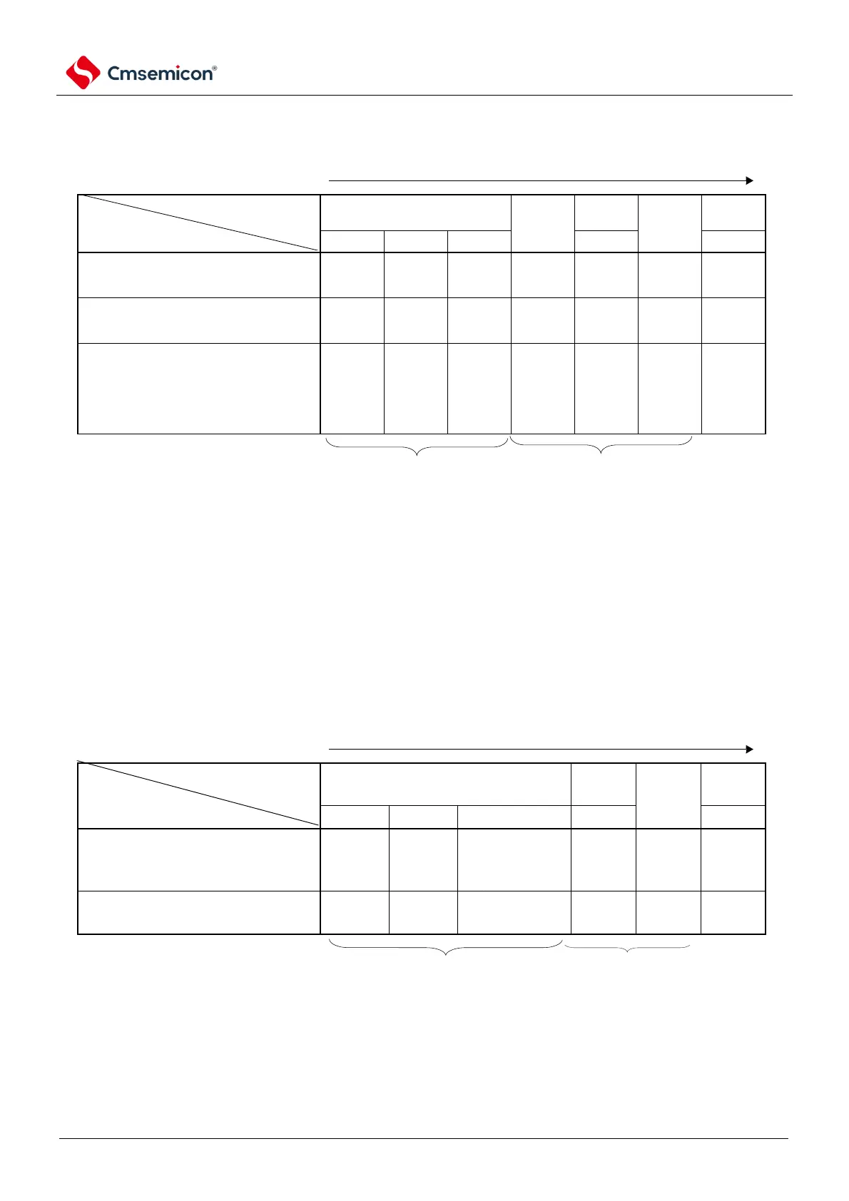
Table 4-3 Example of CPU transfering and SFR register setting (2/5).
(4) The CPU shifts from high-speed internal oscillator clock operation (B) to high-speed system clock
operation (C).
(Order of setting SFR registers).
Not required if set. Not required in high-speed system clock
operation.
Note 1 After the reset is released, only one clock operation mode control register (CMC) can be set. Not required if set.
2. The following settings must be made for the oscillation settling time of the Oscillation Settling Time Selection
Register (OSTS).
the oscillation settling time set by the OSTS register
Note that the clock must be set after the supply voltage reaches the set clock operable voltage (referring to
the electrical characteristics of the data sheet).
(5) The CPU shifts from high-speed internal oscillator clock operation (B) to subsystem clock operation
(D).
(Order of setting SFR registers).
Not required if set. Not required in the operation of the
subsystem clock.
Note that after the reset is released, only one clock operation mode control register (CMC) can be written through the 8-
bit memory operation command. Not required if set.
Note 1 ×: Ignore
2.Table 4-3(A)~(I) correspond to Figure 4-17(A)~(I).