RM0390 Rev 4 699/1328
RM0390 Fast-mode Plus Inter-integrated circuit (FMPI2C) interface
758
The SDA and SCL transition time values to be used are the ones in the application. Using
the maximum values from the standard increases the constraints for the SDADEL and
SCLDEL calculation, but ensures the feature whatever the application.
Note: At every clock pulse, after SCL falling edge detection, the I2C master or slave stretches SCL
low during at least [(SDADEL+SCLDEL+1) x (PRESC+1) + 1] x t
I2CCLK
, in both transmission
and reception modes. In transmission mode, in case the data is not yet written in I2C_TXDR
when SDADEL counter is finished, the I2C keeps on stretching SCL low until the next data
is written. Then new data MSB is sent on SDA output, and SCLDEL counter starts,
continuing stretching SCL low to guarantee the data setup time.
If NOSTRETCH=1 in slave mode, the SCL is not stretched. Consequently the SDADEL
must be programmed in such a way to guarantee also a sufficient setup time.
Additionally, in master mode, the SCL clock high and low levels must be configured by
programming the PRESC[3:0], SCLH[7:0] and SCLL[7:0] bits in the FMPI2C_TIMINGR
register.
• When the SCL falling edge is internally detected, a delay is inserted before releasing
the SCL output. This delay is
t
SCLL
= (SCLL+1) x t
PRESC
where t
PRESC
= (PRESC+1) x
t
I2CCLK.
t
SCLL
impacts the SCL low time t
LOW .
• When the SCL rising edge is internally detected, a delay is inserted before forcing the
SCL output to low level. This delay is
t
SCLH
= (SCLH+1) x t
PRESC
where t
PRESC
=
(PRESC+1) x t
I2CCLK.
t
SCLH
impacts the SCL high time t
HIGH .
Refer to FMPI2C master initialization for more details.
Caution: Changing the timing configuration is not allowed when the FMPI2C is enabled.
The FMPI2C slave NOSTRETCH mode must also be configured before enabling the
peripheral. Refer to FMPI2C slave initialization for more details.
Caution: Changing the NOSTRETCH configuration is not allowed when the FMPI2C is enabled.
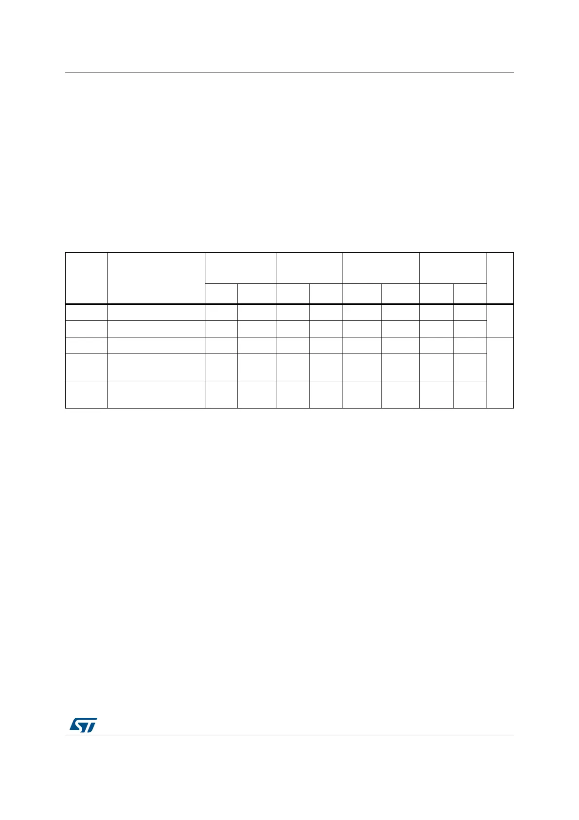
Table 128. I
2
C-SMBUS specification data setup and hold times
Symbol Parameter
Standard-mode
(Sm)
Fast-mode
(Fm)
Fast-mode Plus
(Fm+)
SMBUS
Unit
Min. Max Min. Max Min. Max Min. Max
t
HD;DAT
Data hold time 0-0-0 -0.3-
µs
t
VD;DAT
Data valid time - 3.45 - 0.9 - 0.45 - -
t
SU;DAT
Data setup time 250 - 100 - 50 - 250 -
ns
t
r
Rise time of both SDA
and SCL signals
- 1000 - 300 - 120 - 1000
t
f
Fall time of both SDA
and SCL signals
- 300 - 300 - 120 - 300
 Loading...


