Chapter 13 Replacing Chassis Components 13-7
FIGURE 13-6 Securing Cables Into Routing Clips
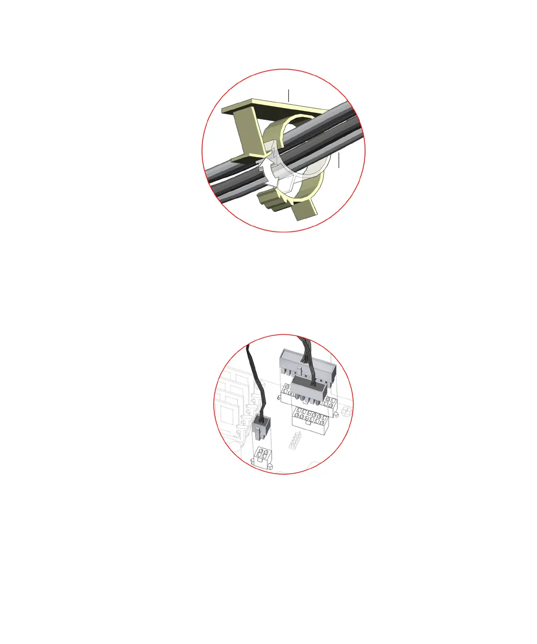
9. Connect the three power supply cables to the motherboard power connectors PS0,
PS1, and PS2.
See FIGURE 13-7.
FIGURE 13-7 Attaching Power Supply Connectors
10. Inspect the power supply fasteners to verify that:
■ The power supply screws are in place and tight.
■ The power supply is well seated in the chassis guides.
11. Inspect the power supply cabling to verify that:
Routing clip
Power
supply
cables
PS0
PS1
PS2