14-20 Sun Blade 1500 Service, Diagnostics, and Troubleshooting Manual • December 2004
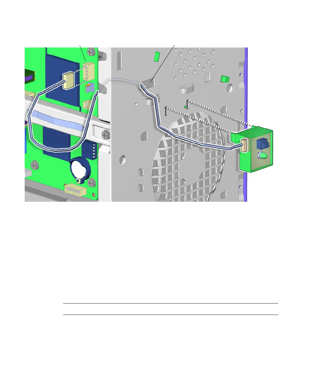
FIGURE 14-18 Removing the Power Switch Assembly
6. Squeeze the tabs on either side of the power switch assembly and tilt it out and
away from the front panel.
See FIGURE 14-18.
7. Lift the power switch assembly up and away from the chassis.
8. Feed the power switch assembly cable through the opening in the front panel as
you lift away the power switch assembly.
See FIGURE 14-18.
Proceed to “Installing the Power Switch Assembly” on page 14-21.
Note – The workstation does not operate without the power switch assembly.
Connector J24 SW0 Rectangular hole