Appendix C Functional Description C-37
modulated outputs control the fan speeds by varying the output duty cycle from
33% to 100%. The speed of each fan is monitored from fan tachometer feedback and
adjusted appropriately.
There are two alarm outputs from ADM1031:
■ Programmable interrupt output, INT#
■ Emergency power-off output, THERM#
The signal from the temperature sensors is analyzed by the OpenBoot PROM which
instructs the ADM1031 to set an optimal fan speed for cooling. Should an overheat
condition occur, an interrupt is triggered to inform the Solaris software of the
situation.
If the temperature exceeds a programmed threshold value, the ADM1031 goes to an
alarm state and sends an emergency power-off interrupt directly to the M1535D+
I/O subsystem, powering off the Sun Blade 1500 workstation to prevent CPU
damage.
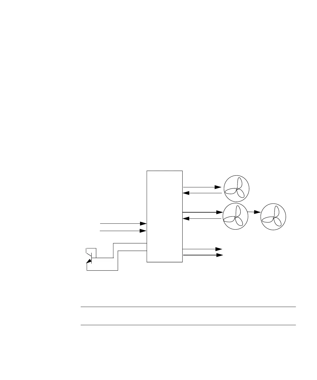
FIGURE C-7 shows a block diagram of the cooling fan control system.
FIGURE C-7 Cooling Fan Control Block Diagram
Note – Though there are two system fans, only the front system fan provides
tachometer feedback to the ADM1031.
CPU Fan
System Fans
PWM1
TACH1
PWM2
TACH2
ADM1031
D0+
D0-
D1+
D1-
SCL
SDA
INT#
IChip2
THERM#
M1535D+ EM_OFF pin
CPU
TEMP_SENSE+
TEMP_SENSE-
Thermal Diode