SUBTASK 53-51-01-100-001
(4) Make sure that the mating surface between the panel conductive surface and the dimpled
washer if installed, is clean.
SUBTASK 53-51-01-100-002
(5) Make sure that the fasteners and the area around the fastener holes are clean.
F. Check the Electrical Resistance of the Designated Bonds
SUBTASK 53-51-01-400-001
(1) Install one fastener, and one dimpled washer in a designated bond location in the panel.
SUBTASK 53-51-01-765-001
(2) Put a dimpled washer only in an adjacent (empty) designated bonded fastener location.
SUBTASK 53-51-01-765-002
(3) Put one probe of a digital/analog multimeter, COM-1793 on the installed designated bonded
fastener head.
SUBTASK 53-51-01-765-003
(4) Put the second probe on a dimpled washer in the adjacent (empty) designated bonded
fastener location.
NOTE: The dimpled washer if installed, completes an electrical bond between the panel
conductive surface and the probe.
SUBTASK 53-51-01-765-004
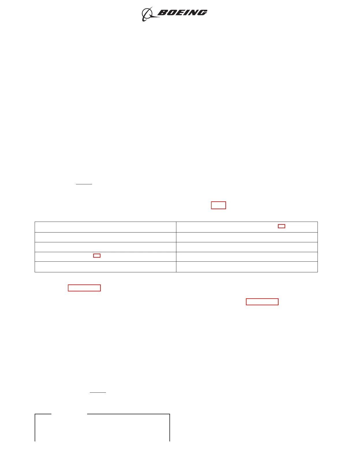
(5) Make sure that the resistance is not more than in the Table 601.
Table 601/53-51-01-993-801 Panel Conductive Surface Maximum Resistance
Conductive Surface Type Maximum Resistance (Ohm)
*[1]
Anti-Static Coating 300,000
Aluminum Coated Fiber 10
Expanded Aluminum Foil
*[2]
0.5
Flamespray 0.5
*[1] Some panels will be installed with bonding jumpers. The dimension of the bonding jumper can change the maximum
resistance. Refer to the installation procedure for the maximum resistance of panels with bonding
jumpers(PAGEBLOCK 53-51-21/401).
*[2] Some panels with the expanded aluminum foil surface can have different maximum resistances. Refer to the
installation procedure for panels with different maximum resistances than in this table (PAGEBLOCK 53-51-21/401).
SUBTASK 53-51-01-765-005
(6) Make sure that the dimpled washer if installed, does not move:
(a) Remove the probe.
(b) Install the fastener.
G. Repeat the Check
SUBTASK 53-51-01-765-006
(1) Repeat the Check of the Electrical Resistance of the Designated Bonds
(a) Do the check with each subsequently installed designated bond fastener as the start
point until all fasteners are installed.
NOTE: It is not necessary to remove or do the resistance check again for the very first
fastener installed.
737-600/700/800/900
AIRCRAFT MAINTENANCE MANUAL
53-51-01
Page 603
D633A101-ILF Feb 15/2018
ECCN 9E991 BOEING PROPRIETARY - Copyright © Unpublished Work - See title page for details
EFFECTIVITY
ILF ALL