(Continued)
Zone Area
114 Area Above and Outboard of Nose Landing Gear Wheel Well - Right
211 Flight Compartment - Left
212 Flight Compartment - Right
E. Access Panels
Number Name/Location
112A Forward Access Door
113AC Fwd Nose Wheel Well Upper Access Panel
114AC Fwd Nose Wheel Well Upper Access Panel
F. Autothrottle Switchpack Assembly Installation
SUBTASK 76-11-07-860-031-F00
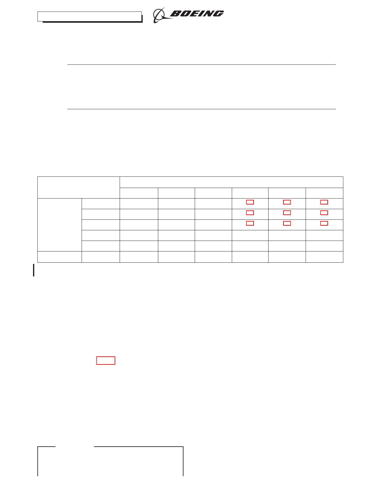
(1) Interchangeability Cross-matrix Table:
ACCEPTABLE COMBINATIONS OF LH & RH AUTOTHROTTLE (A/T) SWITCHPACKS
254A1150-( ) LH A/T SWITCHPACKS
-1 -7 -9 -11 -13 -15
254A1150-( )
RH A/T
SWITCHPACKS
-2 X X X
*[1] *[1] *[1]
-8 X X X
*[1] *[1] *[1]
-10 X X X
*[1] *[1] *[1]
-12 X X X X X X
-14 X X X X X X
-16 X X X X X X
*[1] This combination of switchpacks has the potential for interference between the wires on the P/N 254A1150-2 or -8 or
-10 switchpack and the body of the P/N 254A1150-11 or -13 or -15 switchpack. Assure there is no interference during
installation. If required, protect wiring using the methods outlined in the Standard Wiring Practices Manual (SWPM).
ILF ALL; AUTOTHROTTLE SWITCHPACK WITH REPLACEABLE SWITCHES P/N 254A1150-1, -2, -7,
-8, -9, -10
SUBTASK 76-11-07-420-006-F00
(2) Install a switchpack [9] as follows:
(a) Make sure the Switchpack Assembly is compatible via the interchangeability cross-matrix
table.
(b) Put the switchpack [9] on the bushing [1] of the autothrottle assembly.
(c) Make sure that the missing tooth in the switchpack cam is in the aft direction (View A-A,
Figure 401).
(d) Put the slot of the crank [6] in the up position.
(e) Make sure that the slot in the crank is at 90 degrees to the missing tooth on the shaft.
(f) Install the two bolts [2], washers [14], and nuts [13].
(g) Move the rod [5] into its position on the crank [6].
(h) Install the bolt [4], washer [7], and nut [8].
(i) Make sure that the switchpack wire bundle is held in the applicable wire bundle sheath.
(j) Do the initial alignment of the switchpack as follows:
737-600/700/800/900
AIRCRAFT MAINTENANCE MANUAL
CFM56 ENGINES (CFM56-7)
76-11-07
Page 424
D633A101-ILF Oct 15/2019
ECCN 9E991 BOEING PROPRIETARY - Copyright © Unpublished Work - See title page for details
EFFECTIVITY
ILF ALL