ILF ALL; AUTOTHROTTLE SWITCHPACK WITH REPLACEABLE SWITCHES P/N 254A1150-1, -2, -7, -8, -9, -10
(Continued)
E. Location Zones
Zone Area
112 Area Forward of Nose Landing Gear Wheel Well
113 Area Above and Outboard of Nose Landing Gear Wheel Well - Left
114 Area Above and Outboard of Nose Landing Gear Wheel Well - Right
211 Flight Compartment - Left
212 Flight Compartment - Right
F. Access Panels
Number Name/Location
112A Forward Access Door
G. Autothrottle Switchpack Switch Installation
SUBTASK 76-11-07-420-001-F00
(1) Install the applicable switch [12] on the switchpack [9] as follows:
(a) Install a contact on each wire.
(b) Put a 1 in. (25.4 mm) long RT-876 sleeve, G01148 or Versafit heat shrink tubing, G51210
on each wire set from the switch housing.
(c) Insert the three wires into the associated connector pins as shown below (Table 403):
NOTE: Each switch circuit (NO, C, or NC) is marked on each wire lead.
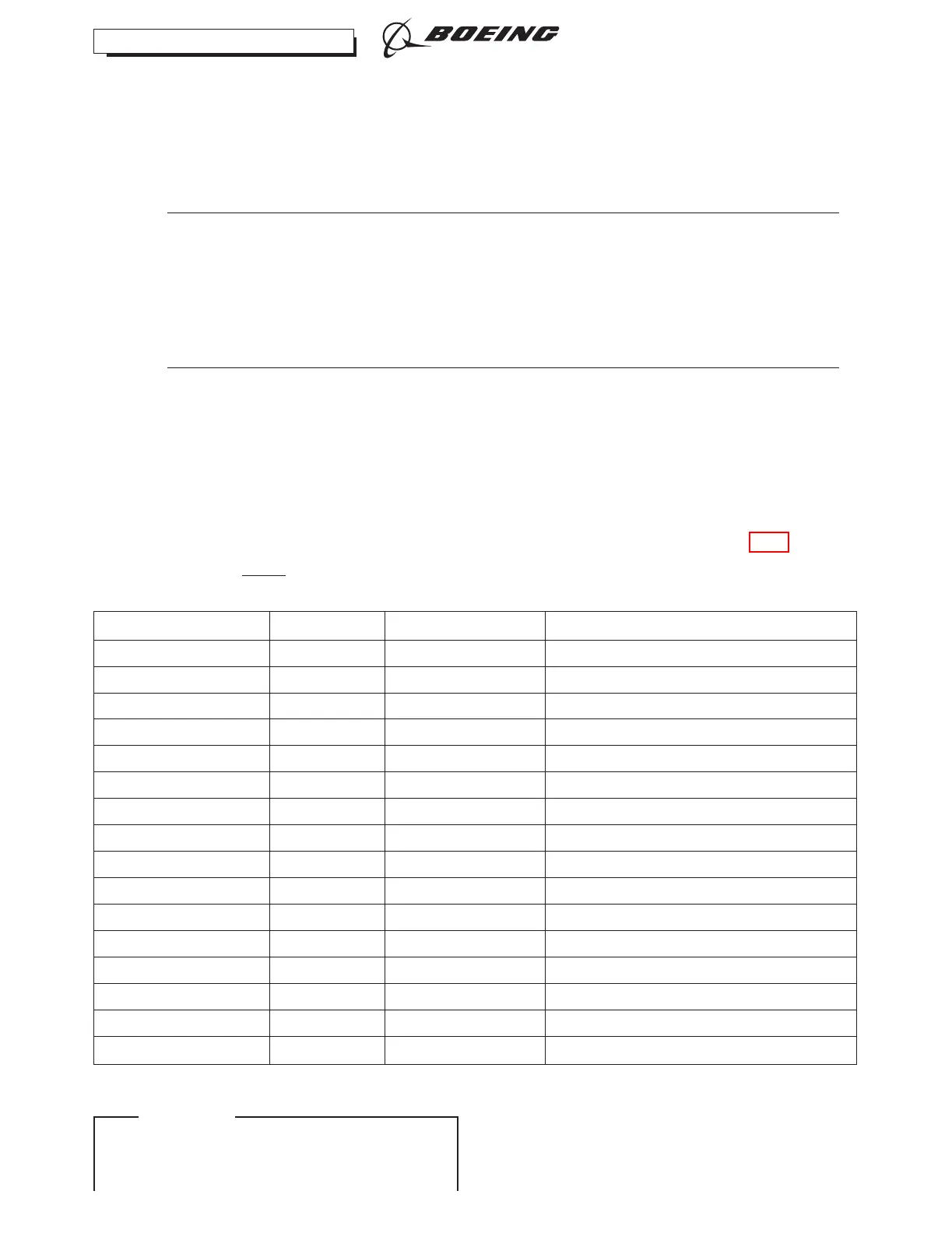
Table 403/76-11-07-993-806-F00
Switchpack Switch Connector Pin (Lead ID)
Left S1 D11128P 1 (NO), 2 (C), 3 (NC)
Left S2 D11130P 1 (NO), 2 (C), 3 (NC)
Left S3 D11130P 4 (NO), 5 (C), 6 (NC)
Left S4 D11128P 14 (NO), 7 (C), 8 (NC)
Left S5 D11130P 7 (NO), 8 (C), 9 (NC)
Left S6 D11130P 13 (NO), 14 (C), 15 (NC)
Left S7 D11128P 10 (NO), 11 (C), 12 (NC)
Left S8 D11128P 16 (NO), 17 (C), 18 (NC)
Left S9 D11128P 22 (NO), 23 (C), 24 (NC)
Right S1 D11132P 1 (NO), 2 (C), 3 (NC)
Right S2 D11134P 1 (NO), 2 (C), 3 (NC)
Right S3 D11134P 4 (NO), 5 (C), 6 (NC)
Right S4 D11132P 14 (NO), 7 (C), 8 (NC)
Right S5 D11134P 7 (NO), 8 (C), 9 (NC)
Right S6 D11134P 13 (NO), 14 (C), 15 (NC)
Right S7 D11132P 10 (NO), 11 (C), 12 (NC)
737-600/700/800/900
AIRCRAFT MAINTENANCE MANUAL
CFM56 ENGINES (CFM56-7)
76-11-07
Page 419
D633A101-ILF Jun 15/2019
ECCN 9E991 BOEING PROPRIETARY - Copyright © Unpublished Work - See title page for details
EFFECTIVITY
ILF ALL