CMS32L051 User Manual |Chapter 23 Voltage Detection Circuit
www.mcu.com.cn 663 / 703
Note 1. After the reset signal is generated, the LVIMK flag changes to 1.
2. When using the interrupt & reset mode, it must be set after the interrupt occurs in accordance with the
Confirmation Figure 23-7 Setup steps for confirmation/reset of the operating voltage.
3. When using interrupt & reset mode, it must be set in accordance with the Figure 23-8 Initial setup steps for
interrupt & reset modeis released.
Note V
POR
: POR supply voltage rise detection voltage
V
PDR
: POR supply voltage drop detection voltage
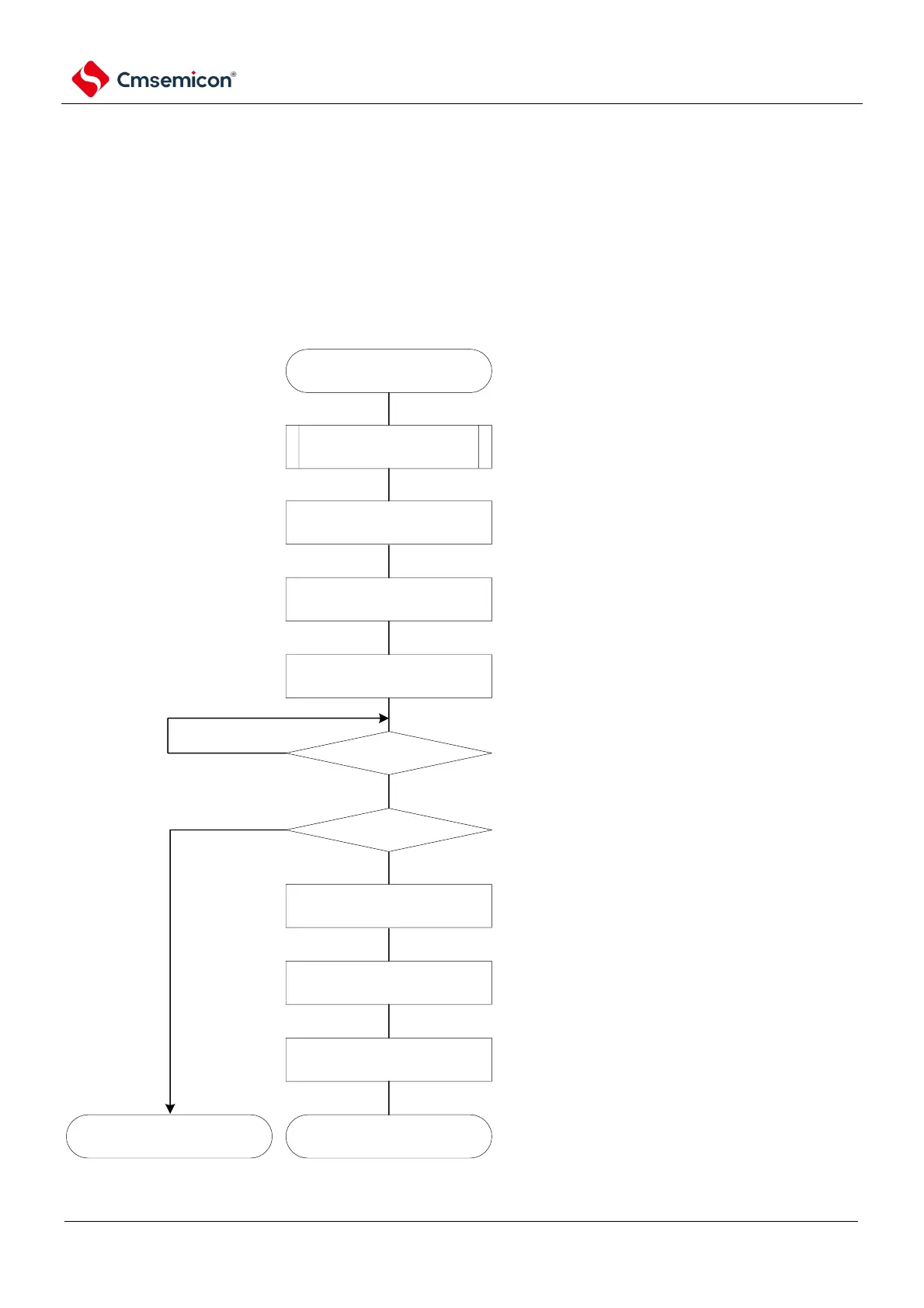
Figure 23-7 Setup steps for confirmation/reset of the operating voltage
set LVILV bit to "0", configure high voltage detection
voltage level (VLVDH)
INTLVI occurs
push stack operation
LVISEN = 1
LVILV = 0
LVISEN = 0
LVIOMSK= 0
LVD reset occurs
LVISEN = 1
LVIMD = 0
LVISEN = 0
normal operation generate LVD internal reset
Yes
No
No
perform necessary push stack operation
set LVISEN bit to "1",mask voltage
detection(LVIOMSK=1).
set LVISEN bit to "0", enable voltage detection
set LVISEN bit to "1",mask voltage
detection(LVIOMSK=1).
set LVIMD bit to "0", configure interrupt mode
set LVISEN bit to "0", enable voltage detection
when LVD circuit did not generate internal reset, it
tells the voltage has recovered to level
VDDVLVDH