46.2.1 Route Redundancy
The basic VRRP applications are illustrated in Figure 47-2.
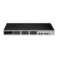
Figure 46-2 Basic VRRP applications
As shown in Figure 47-2, devices A, B and C are connected with the LAN through Ethernet
interfaces, on which the VRRP is configured. They are in the same VRRP group with virtual
IP address 192.168.12.1. Device A is elected as the master device of the VRRP, and devices
B and C are standby. Hosts 1, 2 and 3 in the LAN use the IP address 192.168.12.1 of the
virtual router as the gateway.The packets from the hosts in the LAN to other networks will be
forwarded by the master device (device A in Figure 47-2). Once device A fails, the master
device preempted between devices B and C undertakes the route forwarding function of the
virtual device, resulting in simply route redundancy.
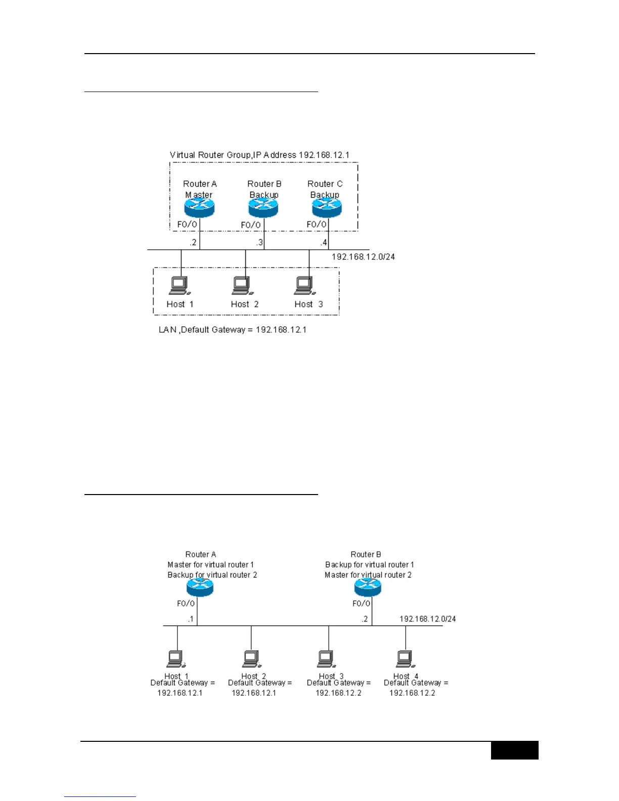
46.2.2 Load Balancing
The advanced VRRP applications are illustrated in Figure 47-3.
Figure 46-3 Advanced VRRP applications