AT-9000 Switch Command Line User’s Guide
649
If you configured the SNMP community strings on the switch, an SNMP
trap is sent to your management workstations to notify you of the event.
However, this event does not generate an entry in the switch’s log.
This feature is supported on the base ports of the switch as well as on any
fiber optic transceivers installed in the unit.
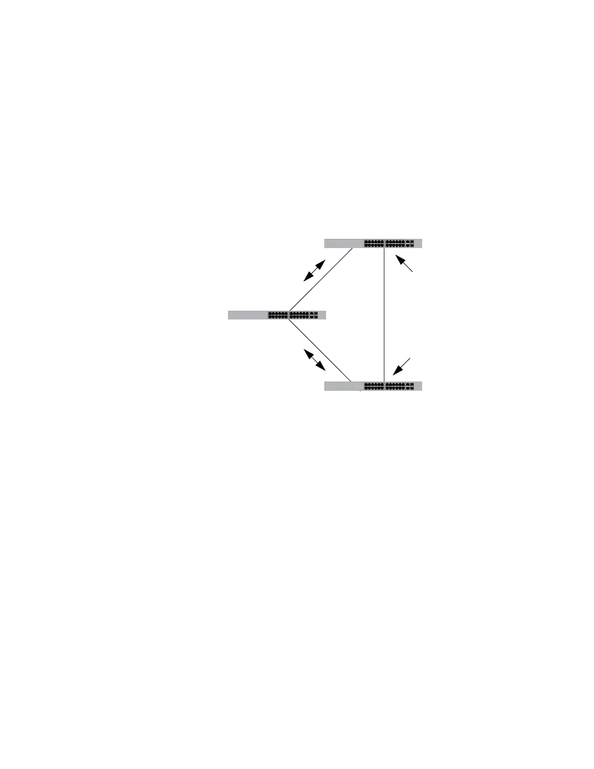
The following figures illustrate this feature. The first figure shows spanning
tree under normal operations in a network of three switches that have
been connected to form a loop. To block the loop, switch 3 designates port
14 as an alternate port and places it in the blocking or discarding state.
Figure 120. Loop Guard Example 1
If port 17 on switch 2 stops transmitting BPDUs, port 14 on switch 3
transitions from the blocking state to the forwarding state because the
switch assumes that the device connected to the port is no longer an
RSTP device. The result is a network loop, as illustrated in Figure 121 on
page 650.
Switch 3
Switch 2
Switch 1
Root bridge
Port 17
Forwarding state
Port 14
Blocking state
 Loading...


