AT-9000 Switch Command Line User’s Guide
Section III: File System 899
VLAN Stacking Process
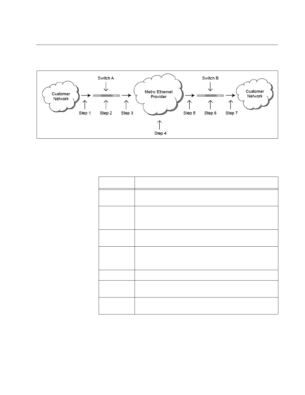
Figure 153 illustrates the VLAN stacking process.
Figure 153. VLAN Stacking Process
The actions are described in Table 82.
Table 82. VLAN Stacking Process
Step Action
1 A tagged or an untagged packet from the customer
network is received by the customer port on switch A.
2 The customer port adds the new 802.1Q header, giving it
the same VID number as the VLAN in which the
customer port is a member.
3 The modified packet is forwarded out the provider port
and into the metro Ethernet provider network.
4 The metro Ethernet provider network forwards the packet
using the VID and EtherType/Length values in the new
header added in step 2.
5 The packet arrives on the provider port on switch B.
6 The customer port deletes the header added in step 2,
returning the packet to its original state.
7 The customer port transmits the packet to the customer
network.
 Loading...


