Chapter 42: STP, RSTP and MSTP Protocols
650
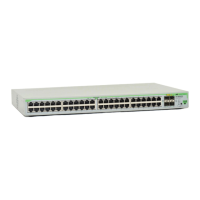
Figure 121. Loop Guard Example 2
But if loop guard is enabled on port 14 on switch 3, the port, instead of
changing to the forwarding state, stays in the blocking state, preventing
the formation of the loop.
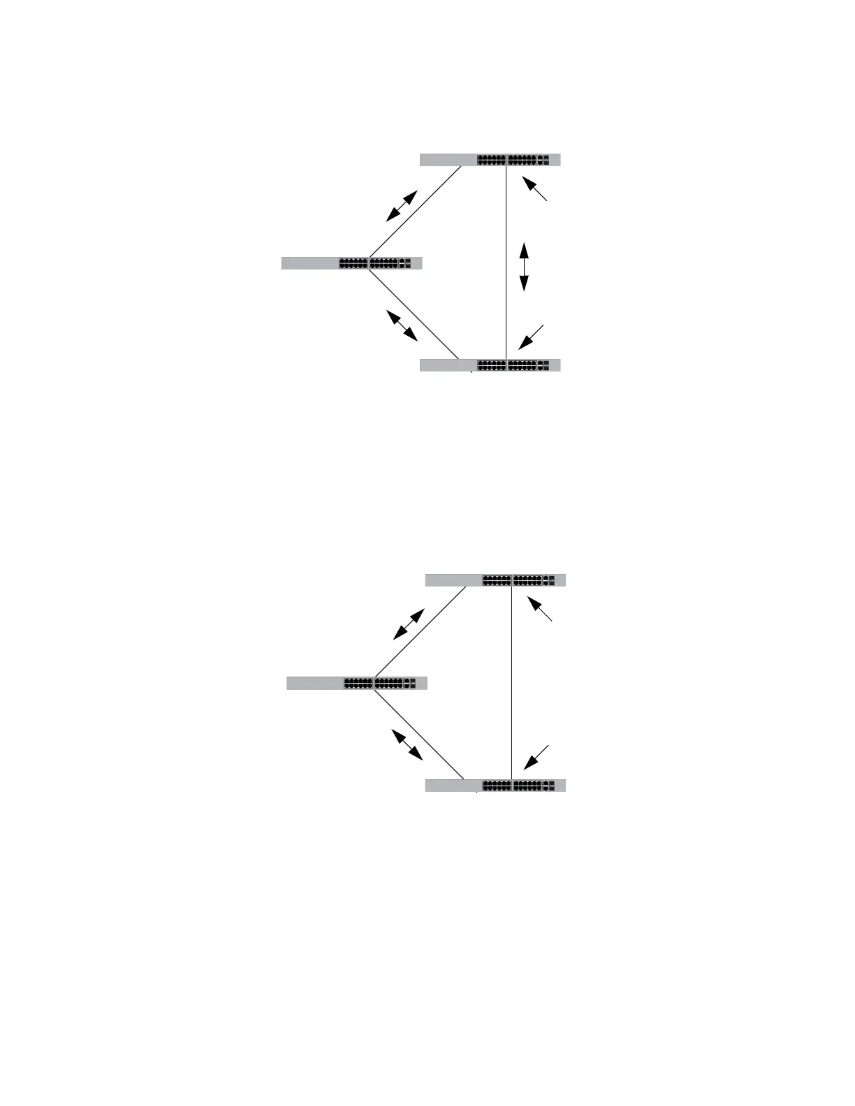
Figure 122. Loop Guard Example 3
The previous example illustrates how loop guard works to maintain a loop-
free topology by keeping alternate ports in the blocking state when they
stop receiving BPDUs. Loop guard can also work on root and designated
ports that are in the forwarding state. This is illustrated in the next two
examples.
Switch 3
Switch 2
Switch 1
Root bridge
Port 17
Stops transmitting BDPUs
Port 14
Transitions to the forwarding
state from the blocking state
Switch 3
Switch 1
Root bridge
Port 17
Stops transmitting BPDUs
Port 14
Loop guard keeps the port
in the blocking state
Switch 2
 Loading...


