For traditional spanning-tree protocol is not related to the VLAN, it will cause the following
problem under specified network topology:
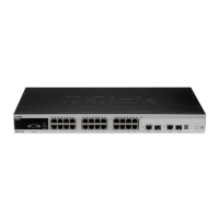
As shown in Figure 17-4, devices A and B are located in Vlan1, and devices C and D in
Vlan2. They form a loop.
Figure 17-14
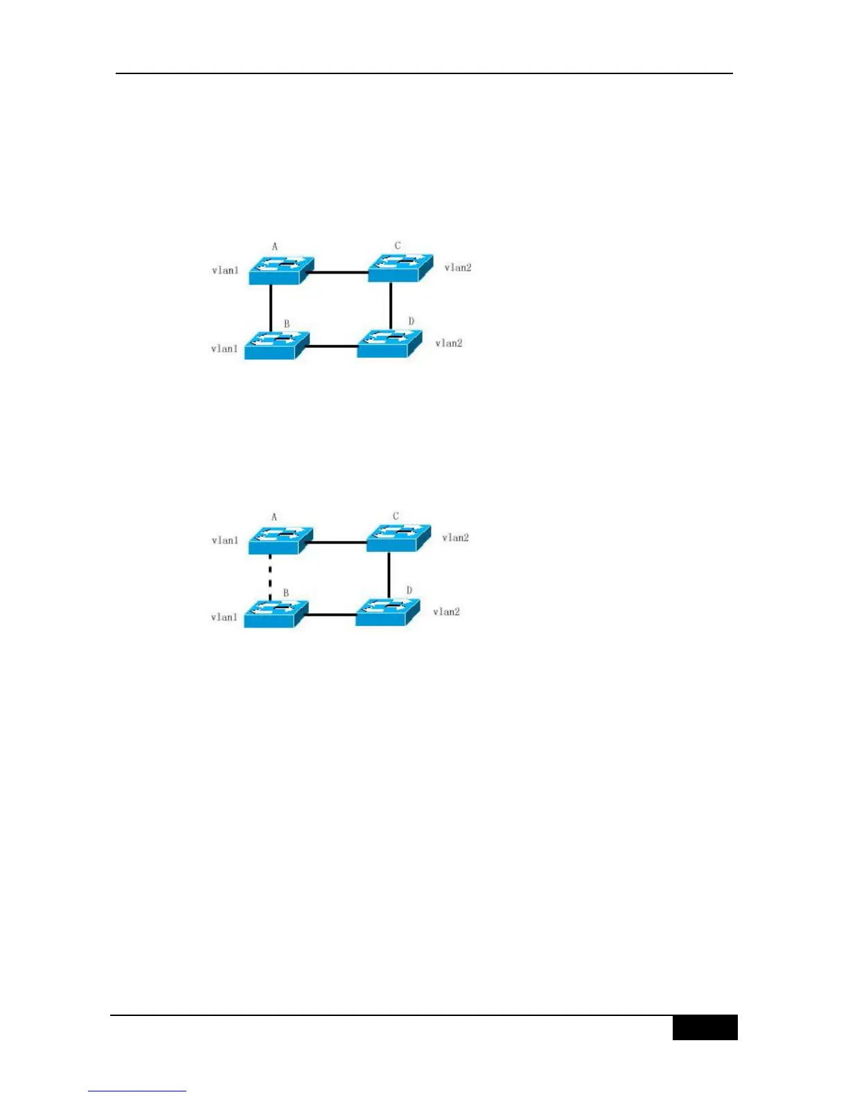
If the link from device A to devices C, D and B has a lower cost than the link from device A to
device B, the link between devices A and B will be discarded (as shown in Figure 17-15).
Packets in Vlan1 will not be forwarded because devices C and D do not contain Vlan1. This
way, Vlan1 of device A cannot communicate with Vlan1 of device B.
Figure 17-15
The MSTP is developed to solve this problem for it can partition one or more vlans of the
switch into an Instance, so the switches with the same Instance configuration form a region
(MST region) to run separate spanning tree (this internal spanning-tree is referred to as the
IST). The combination of the MST region is equivalent to a large device, which executes the
spanning tree algorithm with other MST region to obtain a common spanning tree, referred to
as the common spanning tree (CST).
According to this algorithm, above network can form the topology as Figure 17-16: the
devices A and B are within the MSTP Region 1 and no loop is produced in the MSTP Region
1, so there is no the path DISCARDING. Furthermore, it is the same in the MSTP Region 2
as that in the MSTP region 1. Then, the Region 1 and Region 2 are equivalent to two large
devices respectively and there is no loop between them, so one path is discarded according
to related configuration.